Wiring (continued)
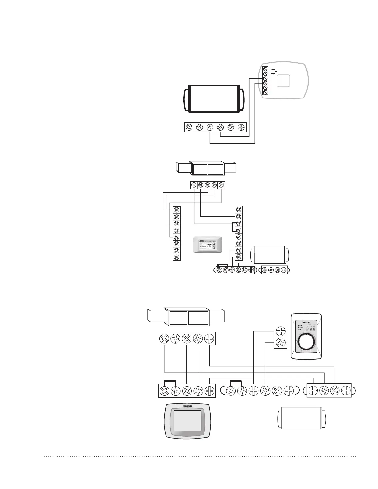
Follow this diagram if using an
external manual dehumidistat.
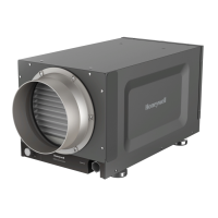
TrueDRY
THERMOSTAT
GYWR C
DHUM
+
+
R
FAN
C
C
Rc
R
H
H
U_
U_
W
W2
Y
Y2
G
K
Gt
+
Rf
Gf
NOTE: THERMOSTAT MUST BE CONFIGURED TO DRIVE FURNACE FAN
DURING DEHUMIDIFICATION CALL.
FLOAT
TrueDRY
MECHANICAL
DEHUMIDISTAT
GYWRRc
GYWR C
M33155
DRY
CONTACTS
Gt
+
+
Rf
Gf
DHUM
+
+
R
FAN
C
FLOAT FLOAT
TrueDRY™ DR65 Dehumidication System 69-2089EFS—14
8
Follow this diagram if using the
Prestige™ thermostat.
Follow this diagram if using the
HumidiPro Digital Humidity Controller.
C
R
U
U
S
S
24 VAC
(CONSTANT)
RFloatDHUM Fan C
 Loading...