Wiring (continued)
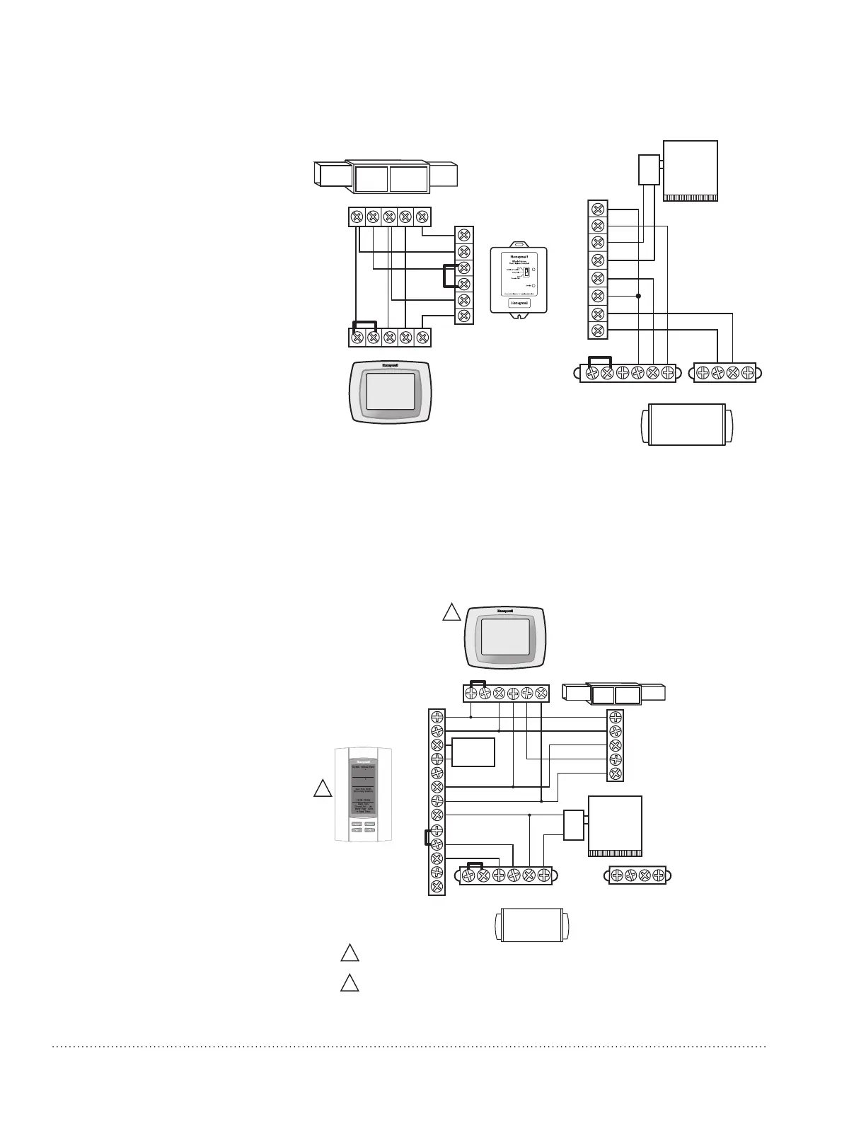
Follow this diagram for ducted opera-
tion with external ventilation control.
TrueDRY
HVAC
THERMOSTAT
GY
W
R
Rc
GYWR C
EARD8TZ
R
C
DAMPER
AUX
REMOTE
W8150A
G
R
C
C
W
G
Gt
+
Rf
Gf
DHUM
+
+
R
FAN
C
FLOAT
HVAC
GYWRRc
IF A THERMOSTAT OTHER THAN A TH5110, TH5220, TH5320, TH6110, TH6220, TH6320, TH8110,
TH8320, OR TH8321 IS USED, A RELAY MAY BE REQUIRED TO ISOLATE THE G WIRE.
PROGRAM ISU SETTING 60 TO Ø TO FORCE SYSTEM FAN ON WITH DEHUMIDIFICATION CALL.
C
68
40
55
1215
:
76
%
%
In
Out
PM
R
C
W
Y
G
R
C
SENSOR
SENSOR
SWITCH
W
G
VENT
VENT
DEHUM
DEHUM
HUM
HUM
OUTDOOR
SENSOR
(PROVIDED)
EARD8TZ
TrueIAQ
1
1
TrueDRY
2
2
Gt
+
+
Rf
Gf
DHUM
+
+
R
FAN
C
FLOAT
TrueDRY™ DR65 Dehumidication System 69-2089EFS—14 9
Follow this diagram if using TrueDRY
DR65 with a powered dehumidistat
such as TrueIAQ (DG115EZIAQ).
 Loading...