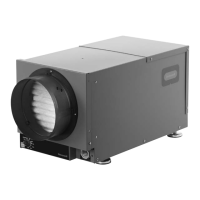
Terminal Description
* NOTE: The outer screws on each
terminal block secure the block to the
chassis. They are not used for wiring.
The six terminals for the left hand terminal block are:
FLOAT (2): External low-voltage water sensor or float
switch
DHUM: Compressor and fan operation for
dehumidification
R: DR65 24V output
FAN: Fan activation only for ventilation
C: DR65 24V output
External 24V devices can be powered from R and C
terminals (20VA max.)
The right hand terminal block in the above figure
is used only for interlocking a TrueDry DR65 with
an equipment fan. The three terminals are:
Gt: Fan operation from thermostat
Rf: 24V from equipment fan
Gf: Fan operation from equipment fan
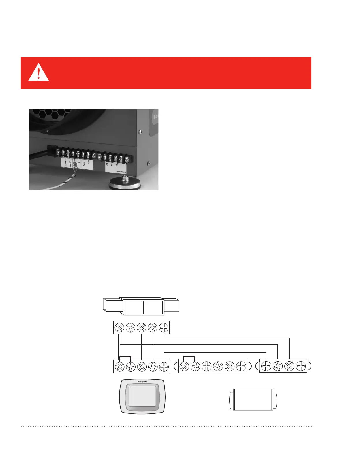
Wiring
Wire the TrueDRY
DR65 according to the
diagram that applies
to your desired opera-
tion.
Follow this diagram for
ducted operation with the
onboard dehumidistat.
Two wiring terminal blocks are located on the exhaust end of the TrueDRY unit.
TrueDRY
THERMOSTAT
GYWRRc
GYWR C
M33153
Gt
+
+
Rf
Gf
DHUM
+
+
R
FAN
C
FLOAT FLOAT
TrueDRY™ DR65 Dehumidication System 69-2089EFS—14 7
CAUTION: Low voltage hazard.
Can cause equipment damage.
Disconnect HVAC equipment before beginning installation.
 Loading...