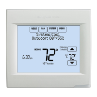
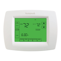
VisionPRO TM 8000 Touchscreen Programmable Thermostat
Table 2. Terminal Designation Descriptions.
Terminal
Designation Description
Rc (see Note Power for cooling--connect to
1) secondary side of cooling system
transformer
R (see Note 1) Power for heating--connect to
secondary side of heating system
transformer
C (see Note 2) Common wire from secondary side of
cooling system transformer
W Heat relay
Y Compressor contactor
G Fan relay
Y2 Second stage cooling
W2 Second stage heat relay
O/B (see Note Changeover valve for heat pump
3) systems
AUX Auxiliary heat relay for heat pump
systems
E Emergency heat relay for heat pump
systems
L (see note 4) Equipment monitor for heat pump
systems
Sl, S2 Optional outdoor or indoor remote
sensor
NOTES:
1.
2.
3.
When used in a single-transformer system, leave
metal jumper wire in place between Rc and R. If
used on a two-transformer system, remove metal
jumper wire between Rc and R.
Common wire is optional when thermostat is used
with batteries.
If thermostat is configured for a heat pump system
in the Installer Setup, configure changeover valve
for cool (O-factory setting) or heat (B).
L terminal is an input (system monitor) when the
System mode is in the Heat, Off, Cool or Auto
position. L terminal is a 24 Vac output when
System mode is Emergency Heat. Must connect
the 24 Vac Common when using the L terminal.
See LED Indication section for more details.
_CONVENTI_NAL
W2
5_1__
L..J,--zsmJ--] i
II
i,
II
II
II
I OUTDOOR/INDOOR I
TEMPERATURE
SENSOR
RC
Y ©
G @ OPTIONAL
24 VAC
COMMON
CONNECTION
pATREL4
A
Z_ POWER SUPPLY PROVIDE DISCONNECT MEANS AND OVERLOAD
PROTECTION AS REQUIRED
Z_ FACTORY INSTALLED JUMPER
A OPTIONAL OUTDOOR OR INDOOR REMOTE SENSOR AVAILABLE
ON SELECT MODELS WIRES MUST HAVE A CABLE SEPARATE
FROM THE THERMOSTAT CABLE M19895
Fig. 9. Typical hookup of conventional single-stage heat
and cool system with single transformer
(IH/lC conventional).
_ CONVENTIONAL
W2
3_1__
II
II
A"
o
I OUTDOOR/INDOC_'_1
TEMPERATURE
SENSOR
G
° o o /,O AL
i COMMON
CONNECTION
IHEATRELAYI
A
A
A POWER SUPPLY PROVIDE DISCONNECT MEANS AND OVERLOAD
PROTECTION AS REQUIRED
Z_ REMOVE FACTORY INSTALLED JUMPER
OPTIONAL OUTDOOR OR INDOOR REMOTE SENSOR AVAILABLE
ON SELECT MODELS WIRES MUST HAVE A CABLE SEPARATE
FROM THE THERMOSTAT CABLE M19896
Fig. 10. Typical hookup of conventional single-stage heat
and cool system with two transformers
(1H/IC conventional).
68-0280 6
 Loading...


