5 Commissioning
Linear actuators MC250 • MC253 • MC500 • MC503
26 Version 2.1 - March 2011 Operating Manual
3 Open the cover (201).
4.4 Fit/remove cover on page 14
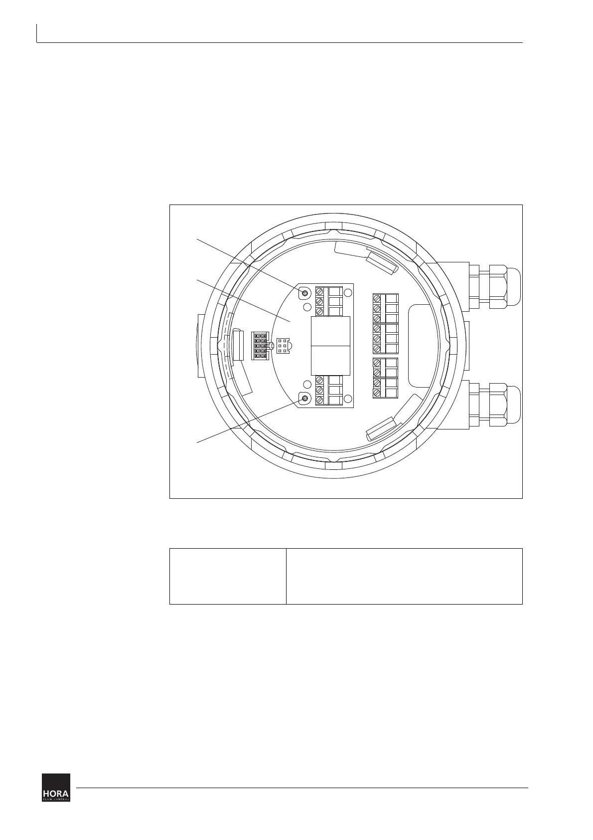
The way-switch printed circuit board is located in the cover (106).
4 Use a screwdriver to turn the trimmer potentiometer until the way-switch
switches. The associated LED goes on or off during this operation.
Use potentiometer P1 (105 P1) to set way-switch 1.
LED 1 indicates the switching status.
Use potentiometer P2 (105 P2) to set way-switch 2.
LED 2 indicates the switching status.
5 Observe the permitted way-switch contact load:
6 Switch off the power supply to the actuator and connect the way-switch contacts.
7 Close the linear actuator (201) cover
Proceed as follows to replace the cover: on page 15
105 P1Trimmer potentiometer 105 P2Trimmer potentiometer
Diagram 19 Way-switch printed circuit board in cover
Nominal load 8 A, 250 V AC
8 A, 30 V DC
Switching voltage max. 400 V AC
max. 125 V DC
Table 6 Way-switch contact load

 Loading...