Hybrid/AC-coupled Inverter User Manual
© 2024 Hoymiles Power Electronics Inc. All rights reserved.
31
3.4.5.2 Smart Meter and CT Connection
The smart meter and CT in the accessory box are necessary for system installation and are used to provide
the operating condition of the inverter via RS485 communication.
Before connecting the smart meter and CT, ensure that the AC cable is totally
isolated from the AC power source.
• One smart meter can be used with only one inverter.
• Three CTs must be used for one smart meter and must be connected on the
same phase with the smart meter power cable.
• There is a symbol (arrow) or label on the surface of CTs that indicates
the correct mechanical orientation of the CT on the conductor under
measurement. Please identify the arrow or label before installing the CT.
• Two smart meters are required for the installation of an AC-coupled system.
There is one smart meter in our packing box, and the other needs to be
purchased from Hoymiles. The meter address is automatically set. If there
are meter communication problems, please check if the address of the PV
side meter is set to 1, and the address of the grid side meter is set to 2.
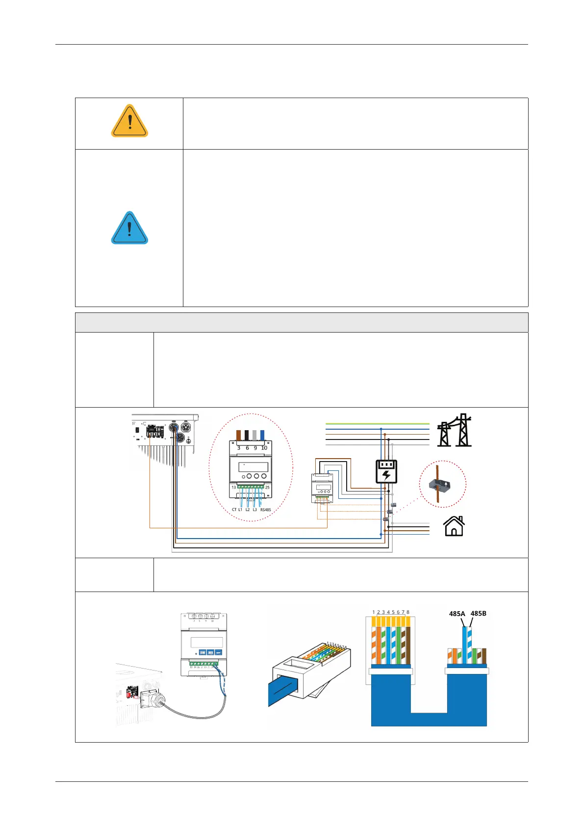
Procedure (for HYT series inverters)
Step 1
• Place the smart meter in or near the grid distribution box, right after the utility
meter.
• Connect grid L1/L2/L3/N to meter’s terminals 3/6/9/10.
• Clamp three CTs to L1/L2/L3 and connect wirings to 13/14, 16/17, and 19/21
respectively. The arrow on the surface of CT should point to the grid.
3(
1
/
/
/
8WLOLW\
0HWHU
56
&7/
&7/
&7/
*ULG
/RDG
6PDUW
0HWHU
/ 1/ /
y
*ULG
6LGH
*ULG
6LGH
Step 2 • Connect the communication cable between the inverter and the smart meter.
485A
485B
NOTICE
WARNING
 Loading...