Hybrid/AC-coupled Inverter User Manual
© 2024 Hoymiles Power Electronics Inc. All rights reserved.
36
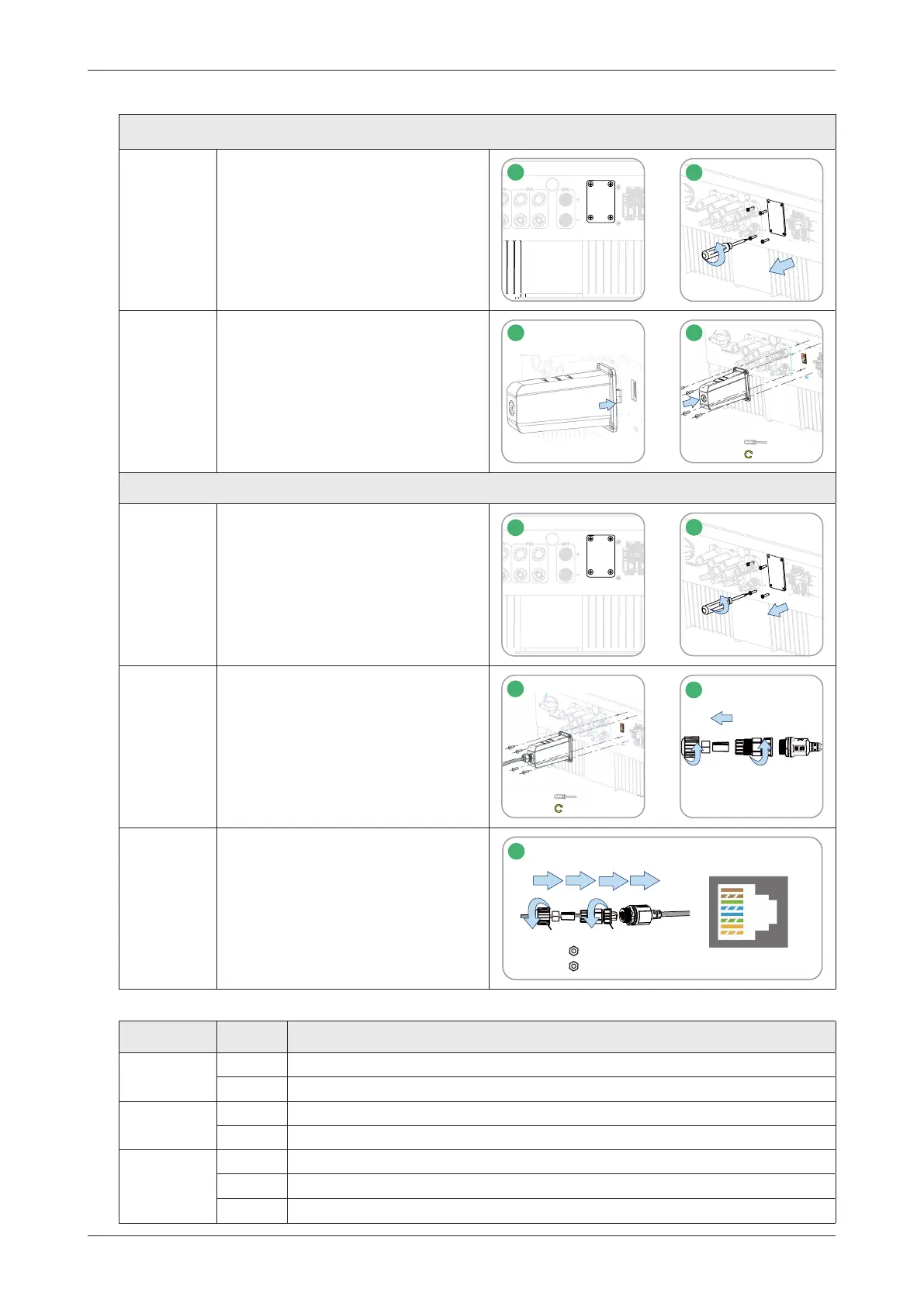
3.4.6 DTS Connection
DTS-WIFI-G1 and DTS-4G-G1 Procedure
Step 1&2 • Remove the DTS port cover plate.
1
USB
2
1
2
Step 3&4
• Insert the DTS into the USB port.
• Fasten the screws.
3
4
M3
0.6-0.8 N·m
DTS-Ethernet-G1 Procedure
Step 1&2 • Remove the DTS port cover plate.
1
USB
2
1
2
Step 3&4
• Insert the DTS-Ethernet into the
USB port, and fasten the screws.
• Unscrew the swivel nut from the
connector.
3
M3
0.6-0.8 N·m
4
1
3
2
Step 5
• Insert the RJ45 plug (pin definition
is shown in the right figure) into
the connector until there is an
audible click sound.
• Thread the cable of an appropriate
length through the connector.
• Tighten the cable gland.
7-NC
6-RX-
5-NC
4-NC
3-RX+
2-TX-
1-TX+
PARA1
0.8-1.5 N·m
0.5-0.8 N·m
2
1
5
5
1
2
3
6
4
2
1
8-NC
Note: The RJ45 plug with cable sheath cannot be inserted.
Indicator Status Description
RUN
ON DTS is powered on.
OFF DTS is not powered on.
COM
ON Proper communication with the inverter.
OFF Improper communication with the inverter.
NET
ON Proper communication with S-Miles Cloud.
OFF Improper communication with S-Miles Cloud
.
BLINK Improper communication with S-Miles Cloud, but the network is connected.
 Loading...