Hybrid/AC-coupled Inverter User Manual
© 2024 Hoymiles Power Electronics Inc. All rights reserved.
34
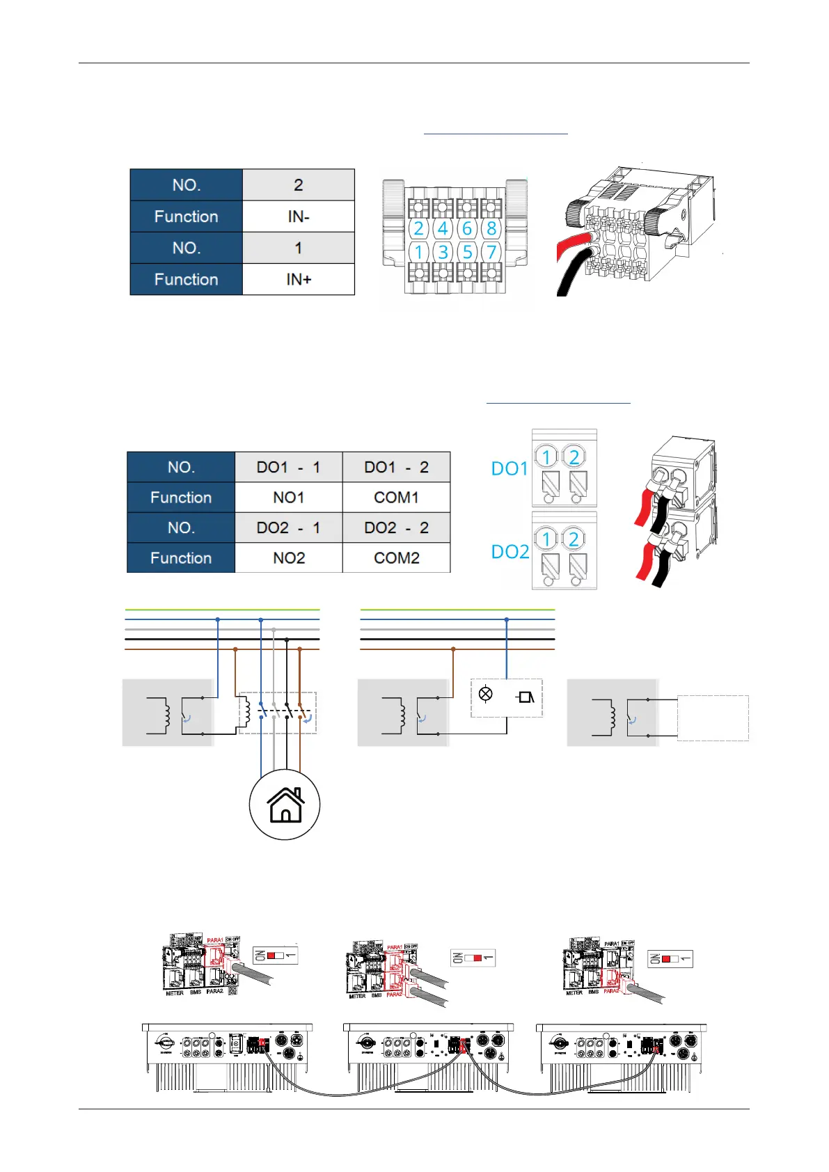
3.4.5.6 Parallel Connection
As shown in the gure, parallel operation is performed through the PARA1/PARA2 interface. When inverters
are used in parallel, the rst and the last inverters are “ON”, and the others are “OFF”.
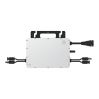
3.4.5.5 DO Connection
The inverter has integrated a multiple-function dry contact (DO1 and DO2). The DO1 can be set to one of
the functions as follows, Earth Fault Alarm, Load Control, and Generator Control. The DO2 can control the
external bypass contactor if used, and for more information, please contact Hoymiles technical support
team. The connection method is the same as that described in “3.4.5.3 DRM Connection”. The function of
each connection position is shown below.
Inverter 1 Inverter 2 Inverter 3
ON OFF
ON OFF
OFFON
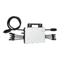
3.4.5.4 DI Connection
There is an integrated DI (IN+, IN-) as the dry contact input to the bypass contactor of the inverter. The
connection method is the same as that described in “3.4.5.3 DRM Connection”. Wiring the No.1 and No.2
holes if used, and the function of each connection position is shown below.
1
/
/
/
1
/
/
/
Inverter
ON
DO1
COM1
NO1
GEN Start-up
N/O Relay
InverterInverter
ON
DO1
COM1
NO1
ON
DO1
COM1
NO1
Load
Contactor
or
light buzzer
DO1-Load Control DO1-Earth Fault Alarm DO1-Generator Control
 Loading...