Hybrid/AC-coupled Inverter User Manual
© 2024 Hoymiles Power Electronics Inc. All rights reserved.
33
Step 2
• Unscrew the communication box
counterclockwise.
• Disassemble the parts in sequence.
1
2
3
2
Step 3
• Strip the insulation layer of the
communication cable, and lead the
corresponding signal cables out. Press
the terminal.
Step 4
• Thread the cable of an appropriate
length through the communication box.
• Clip the cable into the rubber ring.
Step 5
• Plug the wires into the terminal block
firmly according to the following tables.
5
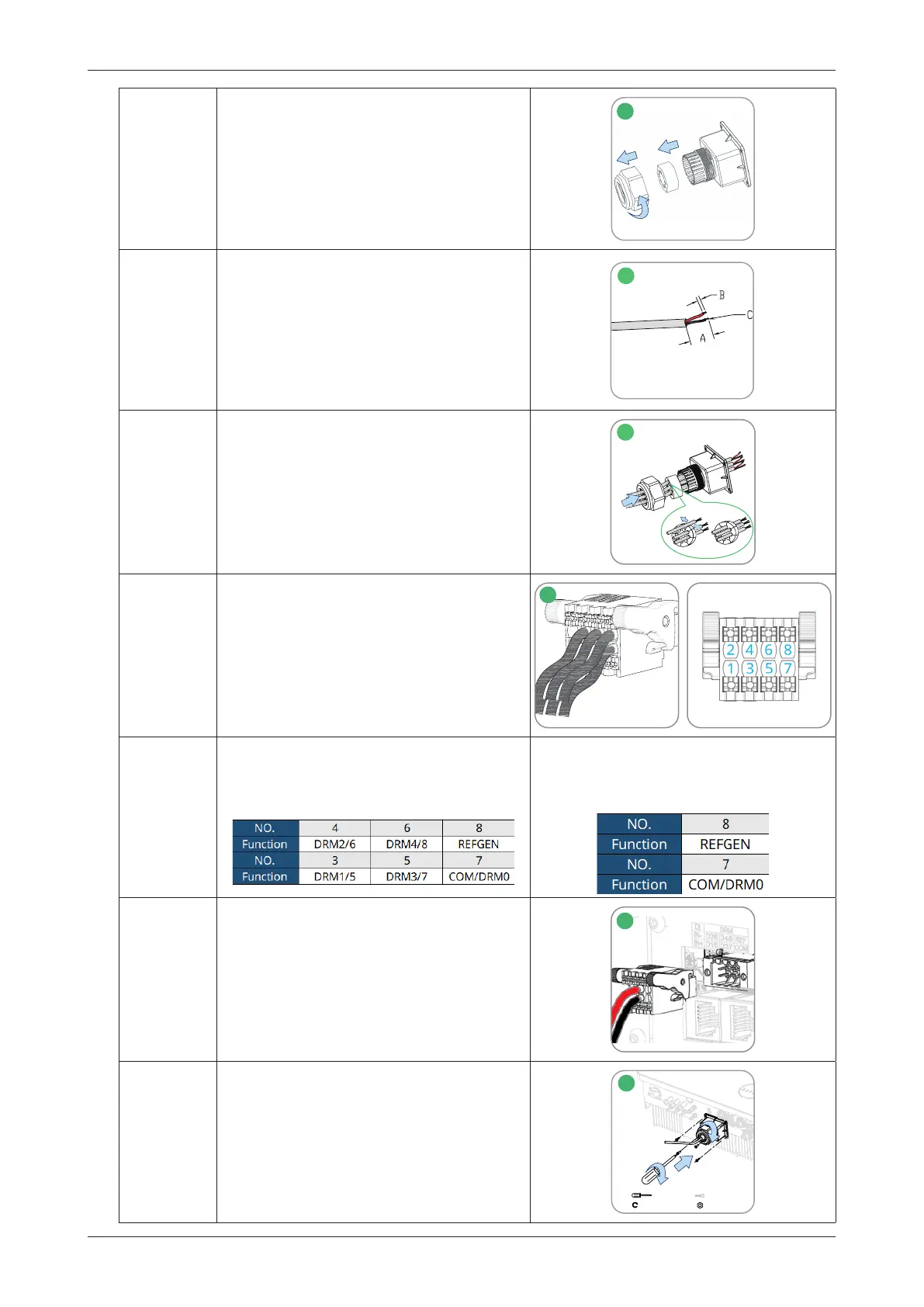
Step 5
• For DRED, wiring from the No.3 to No.8
holes. The function of each connection
position is shown below.
• For Remote Shutdown, wiring the No.7
and No.8 holes. The function of each
connection position is shown below.
Step 6
• Pull the wires outward to check whether
they are fully inserted and cannot be
pulled out easily.
• Insert the terminal block into the
connector until the terminal block clicks
into place.
6
Step 7 • Tighten the cable gland.
1
M3
0.6-0.8 N·m
40 mm
6-7 N·m
2
3
7
A: 35-45 mm B: 7-8 mm
C: 0.2-0.35 mm²
3
 Loading...