155
To allow the MPLS L3VPN traffic to travel the TE tunnel, configure a tunneling policy to use a CR-LSP as
the VPN tunnel when creating the VPN.
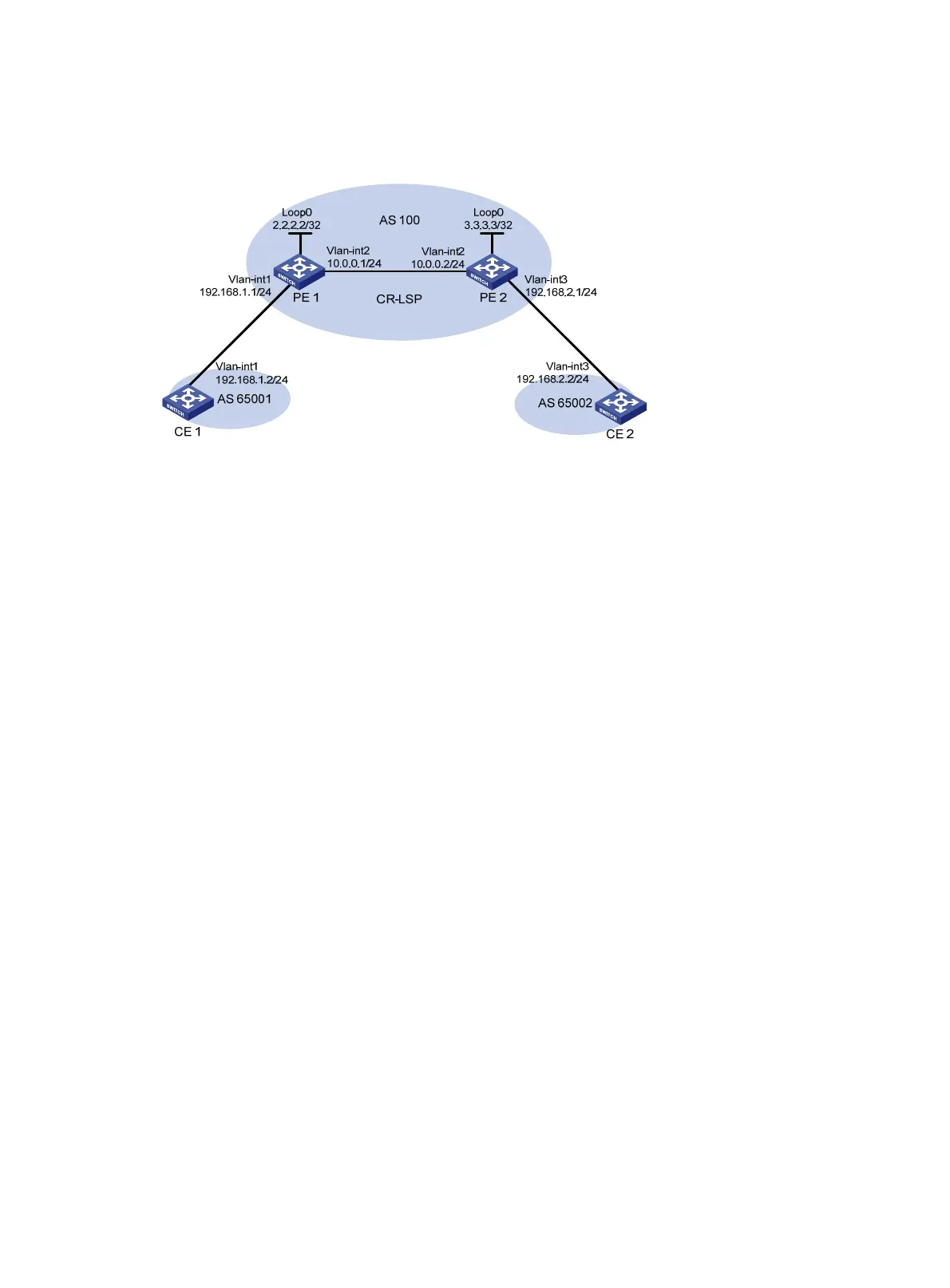
Figure 37 Network diagram
Configuration procedure
1. Configure OSPF, making sure PE 1 and PE 2 can learn LSR-ID routes from each other:
# Configure PE 1.
<PE1> system-view
[PE1] interface loopback 0
[PE1-LoopBack0] ip address 2.2.2.2 255.255.255.255
[PE1-LoopBack0] quit
[PE1] interface vlan-interface 2
[PE1-Vlan-interface2] ip address 10.0.0.1 255.255.255.0
[PE1-Vlan-interface2] quit
[PE1] ospf
[PE1-ospf-1] area 0
[PE1-ospf-1-area-0.0.0.0] network 10.0.0.0 0.0.0.255
[PE1-ospf-1-area-0.0.0.0] network 2.2.2.2 0.0.0.0
[PE1-ospf-1-area-0.0.0.0] quit
[PE1-ospf-1] quit
# Configure PE 2.
<PE2> system-view
[PE2] interface loopback 0
[PE2-LoopBack0] ip address 3.3.3.3 255.255.255.255
[PE2-LoopBack0] quit
[PE2] interface vlan-interface 2
[PE2-Vlan-interface2] ip address 10.0.0.2 255.255.255.0
[PE2-Vlan-interface2] quit
[PE2] ospf
[PE2-ospf-1] area 0
[PE2-ospf-1-area-0.0.0.0] network 10.0.0.0 0.0.0.255
[PE2-ospf-1-area-0.0.0.0] network 3.3.3.3 0.0.0.0
[PE2-ospf-1-area-0.0.0.0] quit
[PE2-ospf-1] quit

 Loading...


