273
For commands to display information about a routing table, see Layer 3—IP Routing Command
Reference.
MPLS L3VPN configuration examples
This section provides examples on how to configure MPLS L3VPN.
Configuring MPLS L3VPNs using EBGP between PE and CE
Network requirements
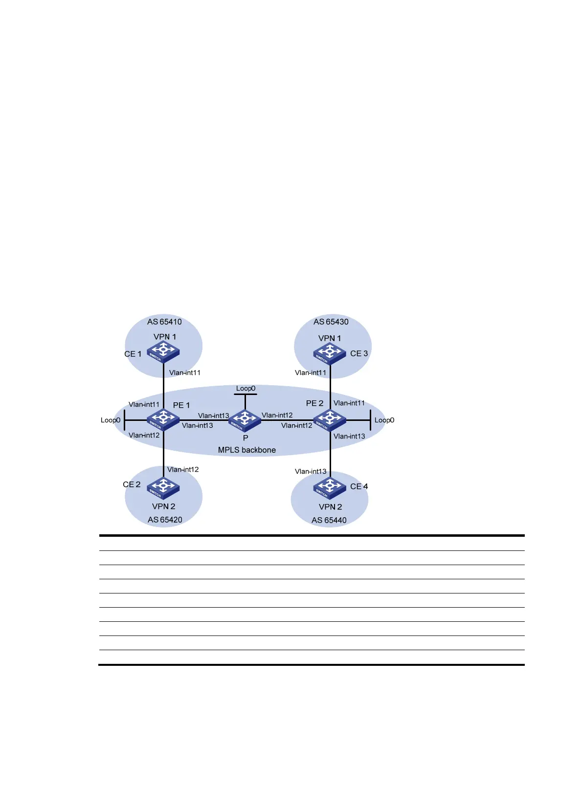
CE 1 and CE 3 belong to VPN 1. CE 2 and CE 4 belong to VPN 2.
VPN 1 uses route target attribute 111:1. VPN 2 uses route target attribute 222:2. Users of different VPNs
cannot access each other.
EBGP is used to exchange VPN routing information between CE and PE.
PEs use OSPF to communicate with each other and use MP-IBGP to exchange VPN routing information.
Figure 31 Network diagram
Device Interface IP address Device Interface IP address
CE 1 Vlan-int11 10.1.1.1/24
P
Loop0
2.2.2.9/32
PE 1 Loop0
1.1.1.9/32
Vlan-int12 172.2.1.1/24
Vlan-int11 10.1.1.2/24 Vlan-int13 172.1.1.2/24
Vlan-int13 172.1.1.1/24
PE 2
Loop0
3.3.3.9/32
Vlan-int12 10.2.1.2/24
Vlan-int12 172.2.1.2/24
CE 2 Vlan-int12 10.2.1.1/24 Vlan-int11 10.3.1.2/24
CE 3 Vlan-int11 10.3.1.1/24
Vlan-int13 10.4.1.2/24
CE 4 Vlan-int13 10.4.1.1/24
Configuration procedure
1. Configure an IGP on the MPLS backbone to ensure IP connectivity within the backbone:
# Configure PE 1.

 Loading...


