380
Reply from 2001:1::2
bytes=56 Sequence=5 hop limit=64 time = 1 ms
--- 2001:1::2 ping statistics ---
5 packet(s) transmitted
5 packet(s) received
0.00% packet loss
round-trip min/avg/max = 1/1/1 ms
Configuring carrier's carrier
Network requirements
Configure carrier's carrier for the scenario shown in Figure 48. In this scenario:
• PE 1 and PE 2 are the provider carrier's PE switches. They provide VPN services for the customer
carrier.
• CE 1 and CE 2 are the customer carrier's switches. They connect to the provider carrier's backbone
as CE switches.
• PE 3 and PE 4 are the customer carrier's PE switches. They provide IPv6 MPLS L3VPN services for
the end customers.
• CE 3 and CE 4 are customers of the customer carrier.
The key to the carrier's carrier deployment is to configure exchange of two kinds of routes:
• Exchange of the customer carrier's internal routes on the provider carrier's backbone.
• Exchange of the end customers' internal routes between PE 3 and PE 4, the PEs of the customer
carrier. In this process, an MP-IBGP peer relationship must be established between PE 3 and PE 4.
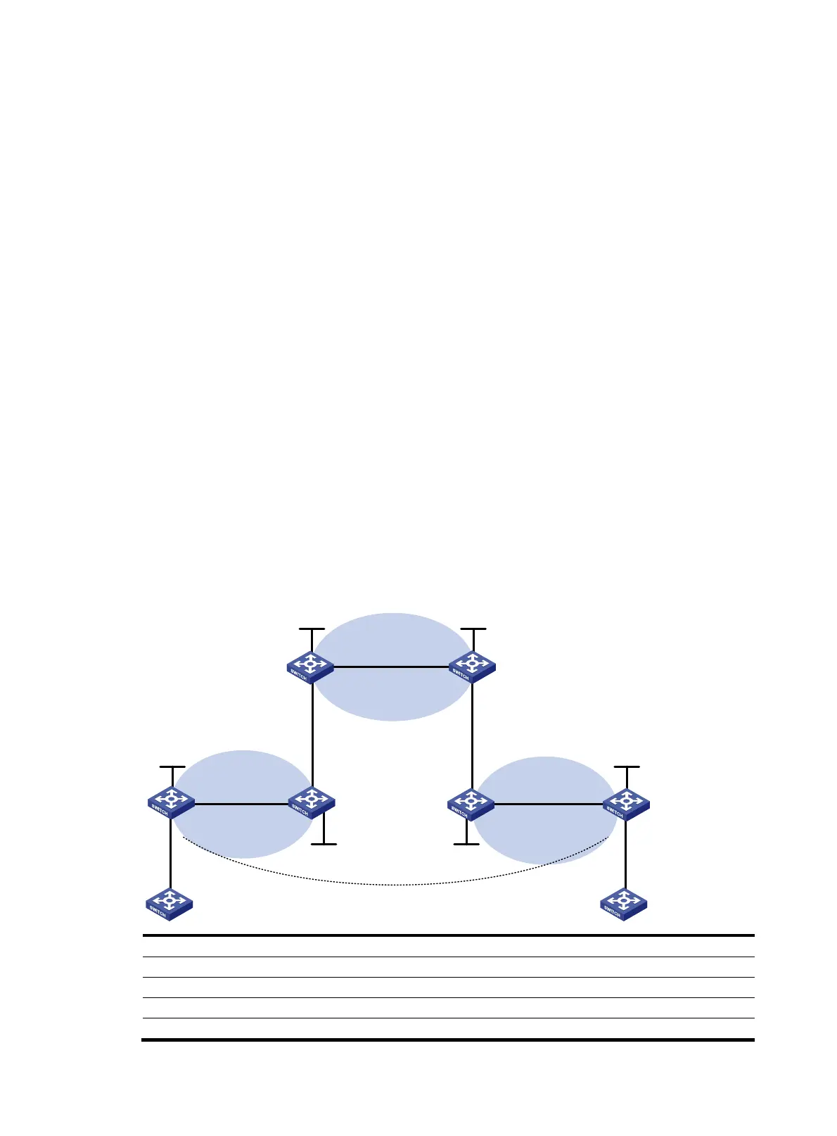
Figure 48 Network diagram
Device Interface IP address Device Interface IP address
CE 3 Vlan-int11 2001:1::1/96
CE 4
Vlan-int11 2001:2::1/96
PE 3 Loop0 1.1.1.9/32
PE 4
Loop0
6.6.6.9/32
Vlan-int11 2001:1::2/96 Vlan-int11 2001:2::2/96
Vlan-int12 10.1.1.1/24
Vlan-int12 20.1.1.2/24
PE 1
PE 2
Provider carrier
Customer carrier
PE 4
CE 2CE 1
PE 3
CE 3
CE 4
AS 65410 AS 65420
Loop0 Loop0
Loop0
Customer carrier
Vlan-int11
Loop0
Loop0
AS 100 AS 100
Vlan-int11
Vlan-int12
Vlan-int12
Vlan-int11
Vlan-int11
Vlan-int12
Vlan-int12
Vlan-int11
Vlan-int11
Vlan-int12
Vlan-int12
Vlan-int11
Vlan-int11
MP-IBGP

 Loading...


