180
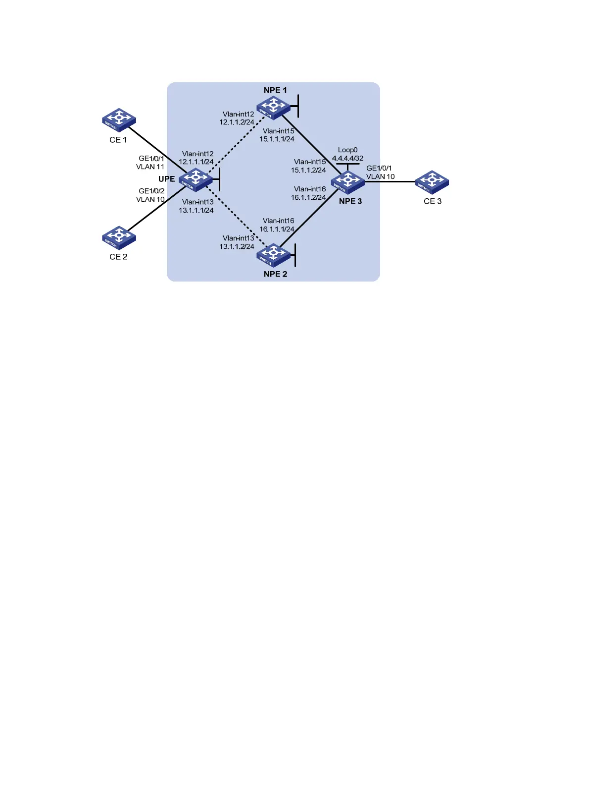
Figure 44 Network diagram
Configuration procedure
1. Configure the IGP protocol on the MPLS backbone. (Details not shown.)
2. Configure UPE:
# Configure basic MPLS.
<Sysname> system-view
[Sysname] sysname UPE
[UPE] interface loopback 0
[UPE-LoopBack0] ip address 1.1.1.1 32
[UPE-LoopBack0] quit
[UPE] mpls lsr-id 1.1.1.1
[UPE] mpls
[UPE-mpls] quit
[UPE] mpls ldp
[UPE-mpls-ldp] quit
# Configure an IP address for the interface connected to NPE 1, and enable MPLS and MPLS LDP.
[UPE] interface vlan-interface 12
[UPE-Vlan-interface12] ip address 12.1.1.1 24
[UPE-Vlan-interface12] mpls
[UPE-Vlan-interface12] mpls ldp
[UPE-Vlan-interface12] quit
# Configure an IP address for the interface connected to NPE 2, and enable MPLS and MPLS LDP.
[UPE] interface vlan-interface 13
[UPE-Vlan-interface13] ip address 13.1.1.1 255.255.255.0
[UPE-Vlan-interface13] mpls
[UPE-Vlan-interface13] mpls ldp
[UPE-Vlan-interface13] quit
# Configure the remote LDP peer NPE 1.
[UPE] mpls ldp remote-peer 1
[UPE-mpls-remote-1] remote-ip 2.2.2.2
[UPE-mpls-remote-1] quit
Loop0
2.2.2.2/32
Loop0
3.3.3.3/32
Loop0
1.1.1.1/32

 Loading...


