223
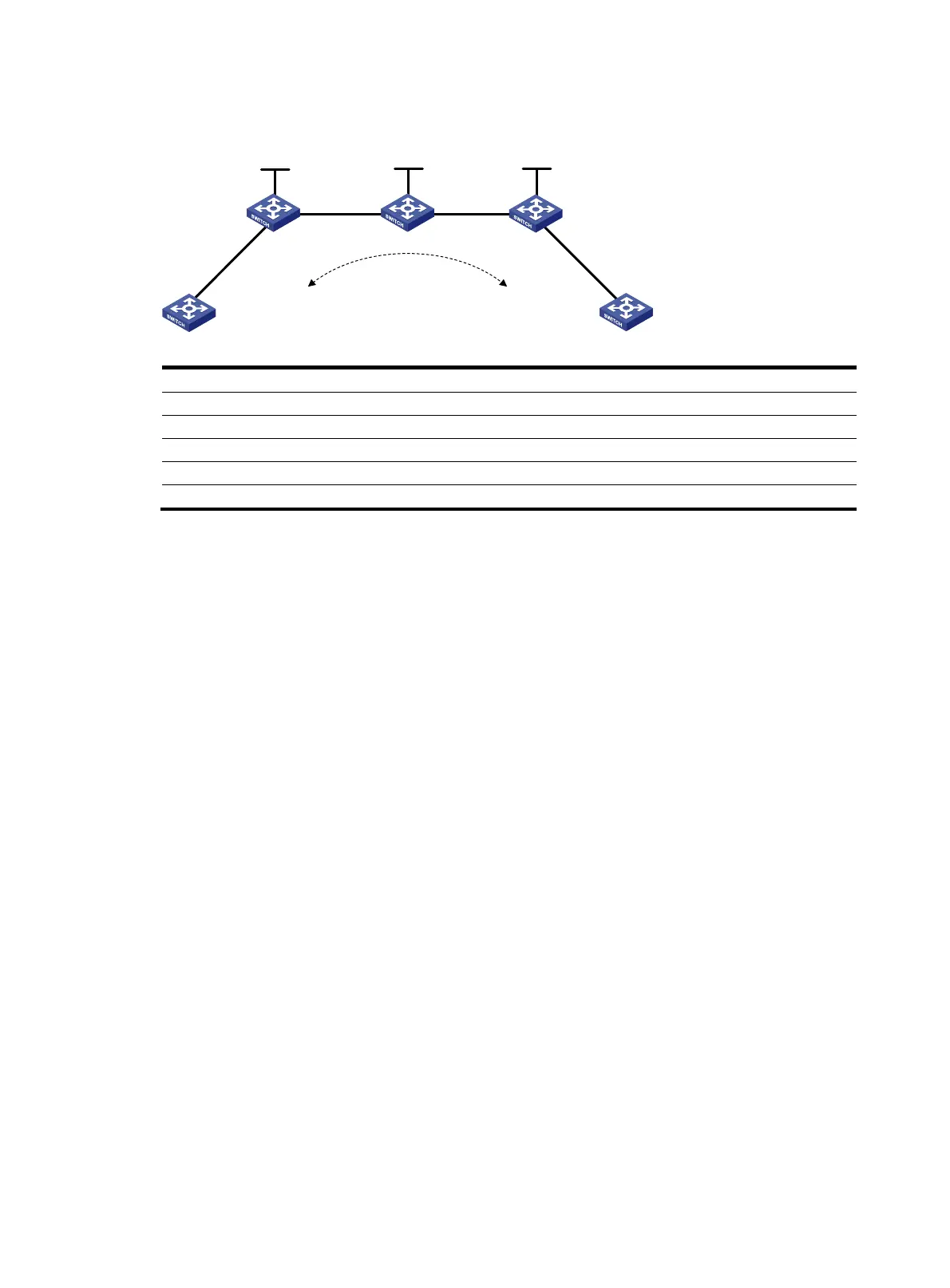
Figure 12 Network diagram
Device Interface IP address
Device
Interface
IP address
CE 1 Vlan-int10 100.1.1.1/24 CE 2 Vlan-int10 100.1.1.2/24
PE 1 Loop0 192.2.2.2/32
P
Loop0
192.4.4.4/32
Vlan-int23 23.1.1.1/24
Vlan-int23 23.1.1.2/24
PE 2 Loop0 192.3.3.3/32 Vlan-int26 26.2.2.2/24
Vlan-int26 26.2.2.1/24
Configuration procedure
1. On CE1, configure an IP address for VLAN-interface 10 connected to PE 1.
<Sysname> system-view
[Sysname] sysname CE1
[CE1] interface vlan-interface 10
[CE1-Vlan-interface10] ip address 100.1.1.1 24
2. Configure PE 1:
# Configure IP address for loopback 0.
<Sysname> system-view
[Sysname] sysname PE1
[PE1] interface loopback 0
[PE1-LoopBack0] ip address 192.2.2.2 32
[PE1-LoopBack0] quit
# Configure the LSR ID and enable MPLS globally.
[PE1] mpls lsr-id 192.2.2.2
[PE1] mpls
[PE1-mpls] quit
# Enable L2VPN and MPLS L2VPN.
[PE1] l2vpn
[PE1-l2vpn] mpls l2vpn
[PE1-l2vpn] quit
# Enable LDP globally.
[PE1] mpls ldp
[PE1-mpls-ldp] quit
# Configure PE 1 to establish an LDP remote session with PE 2.
[PE1] mpls ldp remote-peer 1
[PE1-mpls-ldp-remote-1] remote-ip 192.3.3.3
CE 1
CE 2
Maitini
PE 1 PE 2P
Vlan-int23
Vlan-int23
Vlan-int26
Vlan-int26
Eth1/1 Eth1/1
Vlan-int10
Vlan-int10
Loop0 Loop0 Loop0

 Loading...


