288
Configure OSPF between spoke-PE and hub-PE to ensure IP connectivity between PEs, and configure
MP-IBGP to exchange VPN routing information.
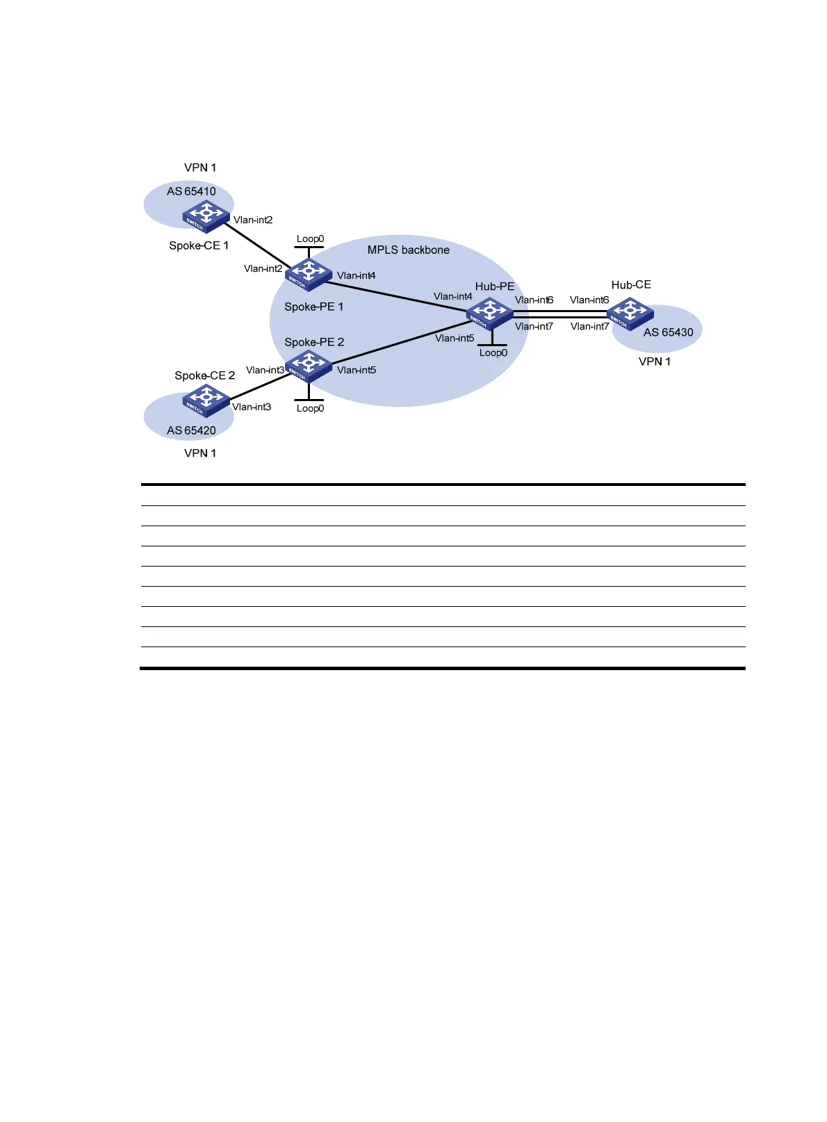
Figure 33 Network diagram
Device Interface IP address
Device
Interface IP address
Spoke-CE 1 Vlan-int2 10.1.1.1/24 Hub-CE Vlan-int6 10.3.1.1/24
Spoke-PE 1 Loop0 1.1.1.9/32
Vlan-int7 10.4.1.1/24
Vlan-int2 10.1.1.2/24
Hub-PE
Loop0
2.2.2.9/32
Vlan-int4 172.1.1.1/24 Vlan-int4 172.1.1.2/24
Spoke-CE 2 Vlan-int3 10.2.1.1/24
Vlan-int5 172.2.1.2/24
Spoke-PE 2 Loop0 3.3.3.9/32
Vlan-int6 10.3.1.2/24
Vlan-int3 10.2.1.2/24 Vlan-int7 10.4.1.2/24
Vlan-int5 172.2.1.1/24
Configuration procedure
1. Configure an IGP in the MPLS backbone to ensure IP connectivity between spoke-PE and hub-PE:
# Configure Spoke-PE 1.
<Spoke-PE1> system-view
[Spoke-PE1] interface loopback 0
[Spoke-PE1-LoopBack0] ip address 1.1.1.9 32
[Spoke-PE1-LoopBack0] quit
[Spoke-PE1] interface vlan-interface 4
[Spoke-PE1-Vlan-interface4] ip address 172.1.1.1 24
[Spoke-PE1-Vlan-interface4] quit
[Spoke-PE1] ospf
[Spoke-PE1-ospf-1] area 0
[Spoke-PE1-ospf-1-area-0.0.0.0] network 172.1.1.0 0.0.0.255
[Spoke-PE1-ospf-1-area-0.0.0.0] network 1.1.1.9 0.0.0.0
[Spoke-PE1-ospf-1-area-0.0.0.0] quit
[Spoke-PE1-ospf-1] quit
# Configure Spoke-PE 2.

 Loading...


