22
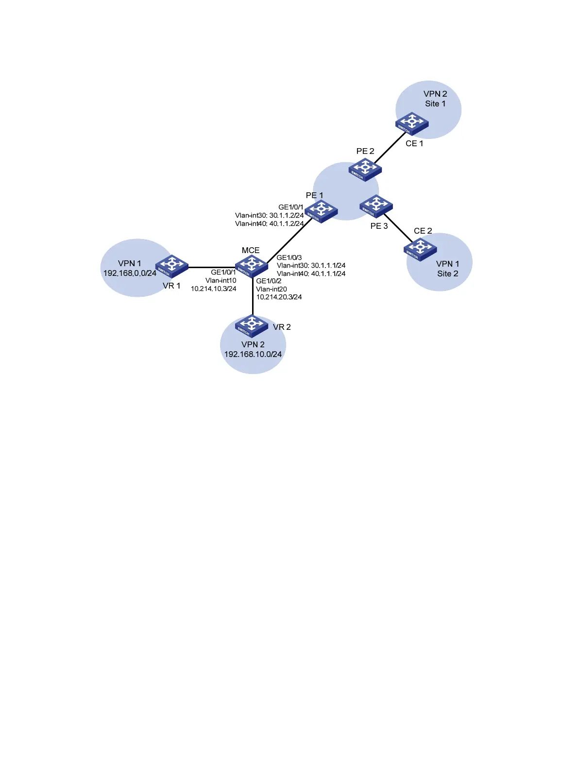
Figure 6 Network diagram
Configuration procedure
Assume that the system name of the MCE device is MCE, the system names of the edge devices of VPN
1 and VPN 2 are VR1 and VR2, respectively, and the system name of PE 1 is PE1.
1. Configure the VPN instances on the MCE and PE 1:
# On the MCE, configure VPN instances vpn1 and vpn2, and specify an RD and VPN targets for
each VPN instance.
<MCE> system-view
[MCE] ip vpn-instance vpn1
[MCE-vpn-instance-vpn1] route-distinguisher 10:1
[MCE-vpn-instance-vpn1] vpn-target 10:1
[MCE-vpn-instance-vpn1] quit
[MCE] ip vpn-instance vpn2
[MCE-vpn-instance-vpn2] route-distinguisher 20:1
[MCE-vpn-instance-vpn2] vpn-target 20:1
[MCE-vpn-instance-vpn2] quit
# Create VLAN 10, add port GigabitEthernet 1/0/1 to VLAN 10, and create VLAN-interface 10.
[MCE] vlan 10
[MCE-vlan10] port gigabitethernet 1/0/1
[MCE-vlan10] quit
[MCE] interface vlan-interface 10
# Bind VLAN-interface 10 with VPN instance vpn1, and configure an IP address for
VLAN-interface 10.

 Loading...


