296
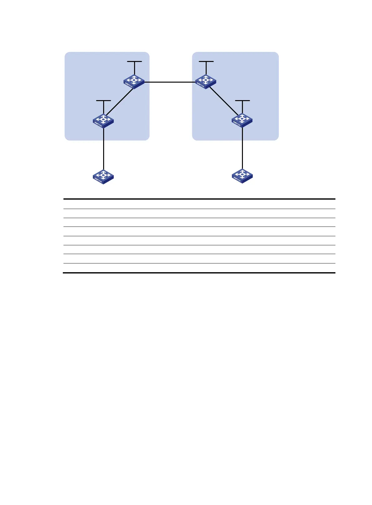
Figure 34 Network diagram
Device Interface IP address
Device
Interface IP address
CE 1 Vlan-int12 10.1.1.1/24 CE 2 Vlan-int12 10.2.1.1/24
PE 1 Loop0 1.1.1.9/32
PE 2
Loop0
4.4.4.9/32
Vlan-int12 10.1.1.2/24
Vlan-int12 10.2.1.2/24
Vlan-int11 172.1.1.2/24 Vlan-int11 162.1.1.2/24
SBR-PE 1 Loop0 2.2.2.9/32
SBR-PE 2
Loop0
3.3.3.9/32
Vlan-int11 172.1.1.1/24
Vlan-int11 162.1.1.1/24
Vlan-int12 192.1.1.1/24 Vlan-int12 192.1.1.2/24
Configuration procedure
1. Configure an IGP on the MPLS backbone to ensure IP connectivity in the backbone.
This example uses OSPF. (Details not shown.)
The 32-bit loopback interface address used as the LSR ID must be advertised by OSPF.
After you complete the configurations, each ASBR PE and the PE in the same AS can establish
OSPF adjacencies. Issue the display ospf peer command. The output shows that the adjacencies
reach Full state, and that PEs can learn the routes to the loopback interfaces of each other.
Each ASBR PE and the PE in the same AS can ping each other.
2. Configure basic MPLS and MPLS LDP on the MPLS backbone to establish LDP LSPs:
# Configure basic MPLS on PE 1 and enable MPLS LDP on the interface connected to ASBR PE 1.
<PE1> system-view
[PE1] mpls lsr-id 1.1.1.9
[PE1] mpls
[PE1-mpls] quit
[PE1] mpls ldp
[PE1-mpls-ldp] quit
[PE1] interface vlan-interface 11
[PE1-Vlan-interface11] mpls
[PE1-Vlan-interface11] mpls ldp
Loop0 Loop0
Loop0 Loop0
Vlan-int12
CE 1 CE 2
AS 65001 AS 65002
PE 1
PE 2
ASBR-PE 2
ASBR-PE 1
MPLS backbone
MPLS backbone
AS 100
AS 200
Vlan-int12
Vlan-int12
Vlan-int12
Vlan-int11
Vlan-int11
Vlan-int12Vlan-int12
Vlan-int11
Vlan-int11

 Loading...


