301
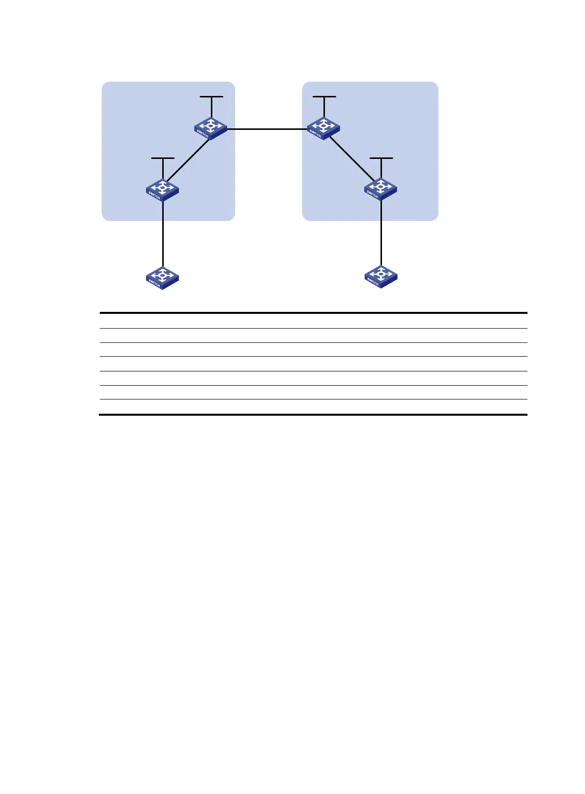
Figure 35 Network diagram
Device Interface IP address
Device
Interface IP address
PE 1 Loop0 2.2.2.9/32 PE 2 Loop0 5.5.5.9/32
Vlan-int12 30.0.0.1/8
Vlan-int12 20.0.0.1/8
Vlan-int11 1.1.1.2/8
Vlan-int11 9.1.1.2/8
ASBR-PE 1 Loop0 3.3.3.9/32 ASBR-PE 2 Loop0 4.4.4.9/32
Vlan-int11 1.1.1.1/8
Vlan-int11 9.1.1.1/8
Vlan-int12 11.0.0.2/8
Vlan-int12 11.0.0.1/8
Configuration procedure
1. Configure PE 1:
# Run IS-IS on PE 1.
<PE1> system-view
[PE1] isis 1
[PE1-isis-1] network-entity 10.1111.1111.1111.1111.00
[PE1-isis-1] quit
# Configure LSR ID, enable MPLS and LDP.
[PE1] mpls lsr-id 2.2.2.9
[PE1] mpls
[PE1-mpls] label advertise non-null
[PE1-mpls] quit
[PE1] mpls ldp
[PE1-mpls-ldp] quit
# Configure interface VLAN-interface 11, and start IS-IS and enable MPLS and LDP on the
interface.
[PE1] interface vlan-interface 11
[PE1-Vlan-interface11] ip address 1.1.1.2 255.0.0.0
[PE1-Vlan-interface11] isis enable 1
[PE1-Vlan-interface11] mpls
Loop0 Loop0
Loop0 Loop0
CE 1 CE 2
AS 65001 AS 65002
PE 1
PE 2
ASBR-PE 2
ASBR-PE 1
MPLS backbone
MPLS backbone
AS 100
AS 600
Vlan-int12
Vlan-int12
Vlan-int11
Vlan-int11
Vlan-int12Vlan-int12
Vlan-int11
Vlan-int11
Site 1 Site 2

 Loading...


