27
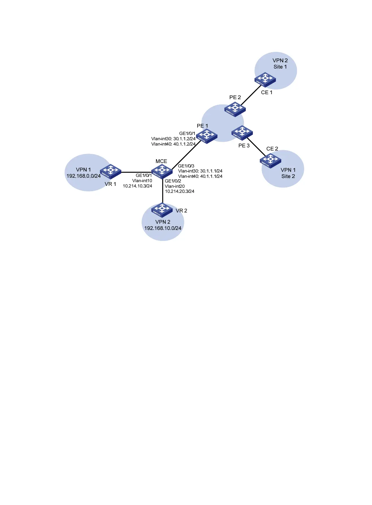
Figure 7 Network diagram
Configuration procedure
1. Create VPN instances on the MCE and PE 1, and bind the VPN instances with VLAN interfaces in
the same way as that described in "Using OSPF to advertise VPN routes to the PE." (Details not
shown.)
2. Configure routing between the MCE and VPN sites:
# Start an OSPF process on the devices in the two VPNs and advertise the subnets. (Details not
shown.)
# Configure OSPF on the MCE, and bind OSPF process 10 with VPN instance vpn1 to learn the
routes of VPN 1.
<MCE> system-view
[MCE] ospf router-id 10.214.10.3 10 vpn-instance vpn1
[MCE-ospf-10] area 0
[MCE-ospf-10-area-0.0.0.0] network 10.214.10.0 0.0.0.255
# Display the routing table of VPN 1 on the MCE.
[MCE-ospf-10-area-0.0.0.0] display ip routing-table vpn-instance vpn1
Routing Tables: vpn1
Destinations : 5 Routes : 5
Destination/Mask Proto Pre Cost NextHop Interface
10.214.10.0/24 Direct 0 0 10.214.10.3 Vlan10
10.214.10.3/32 Direct 0 0 127.0.0.1 InLoop0
127.0.0.0/8 Direct 0 0 127.0.0.1 InLoop0

 Loading...


