Model209A
Section
VII
SECTION
VII
CIRCUIT
DIAGRAMS
7-1.
INTRODUCTION.
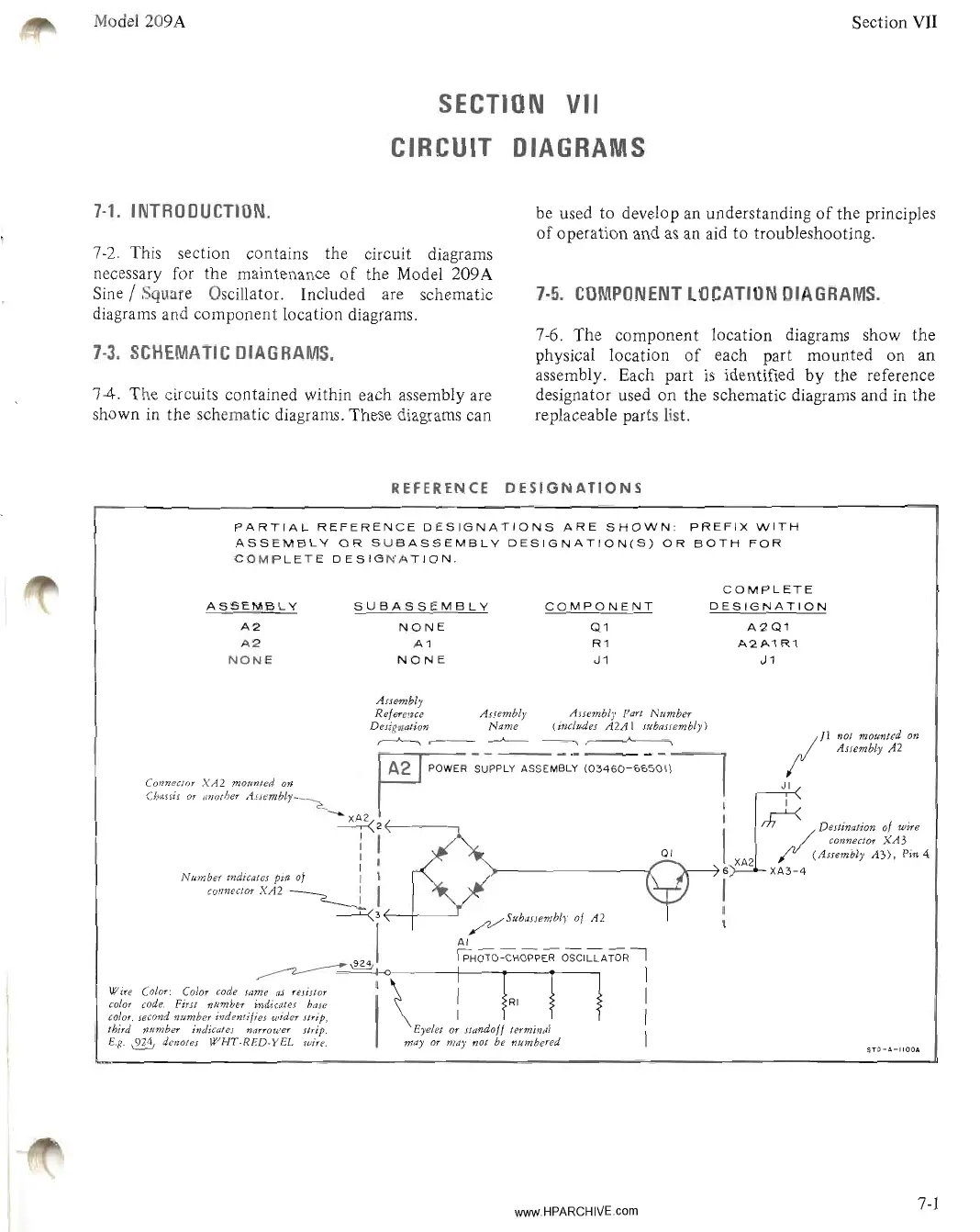
7-2. This section contains the circuit diagrams
necessary for the maintenance
of
the Model 209A
Sine / Square Oscillator. Included are schematic
diagrams and component location diagrams.
7-3.
SCHEMATIC
DIAGRAMS.
74.
The circuits contained within each assembly are
shown
in
the schematic diagrams. These diagrams can
REFERENCE
be used to develop
an
understanding
of
the principles
of
operation and
as
an aid to troubleshooting.
7-5.
COMPONENT
LOCATION
DIAGRAMS.
7-6. The component location diagrams show the
physical location
of
each part mounted on an
assembly. Each part
is
identified by the reference
designator used on the schematic diagrams and in the
replaceable parts list.
DESIGNATIONS
PARTIAL
REFERENCE
DESIGNATIONS
ARE
SHOWN:
PREFIX
WITH
ASSEMBLY
OR
SUBASSEMBLY
DESIGNATION(S)
OR
BOTH
FOR
COMPLETE
DESIGNATION.
ASSEMBLY
A2
A2
NONE
SUBASSEMBLY
NONE
A1
NONE
COMPONENT
Q1
R1
J1
COMPLETE
DESIGNATION
A2Q1
A2A1
R1
J1
STO-A-IIOOA
AJJembly
Reference AJJembly AJJembly
Part
Number
Designation Name (i"cludes
A2AI
subassembly)
,-----"--.,
~
IIInot mounted on
• , AJJembly
A2
IA2 ,
",w,"
~;;;;;:;;;;.;,;
IOH"-';;;'~
Connector
XA2
mounted
on
I J I
Chams
or
",lOther
,1JJembly~
I
~
XA2
I
,........L-(
~
2 I
rh~'
Destmatton of
w"e
I I connector
XA
3
: QI (Assembly
A3).
Pm 4
I I 6 XA2
XA3-4
Number mdlCates
pm
of
I I I
connector
XA2
~
I
----l:{3~__+----l
~SubaJJemblY
of
A2
:
I
AI
!PHOTO-CHOPPER
OSCILLATORI
~~
I
Wire Color: Color code lame
aJ
resistor I \ I
c%r
code. First number indicate! bale I
color, second number
indentifi~J
wider
strip, I I
third number indicates narrower Jtrip. Eyelet or standoff terminal I
E.g.
~
denotes
WHT-RED-YEL
wire.
mayor
may not be "umbered
www.HPARCHIVEcom
7-1