•
•
•
8-98.
When
an
Sm
or
Rm
input
is
at its internal 0
state,
it
has
no
effect.
8-99.
Note
that the
noncomplementary
output
pat-
terns in
cases
4 and 5 are
only
pseudostable. The
simultaneous
return
of
the
inputs
to
S=R=O
produces
an
unforeseeable stable and
complementary
output
pattern.
8-100. EN
(ENABLE)
DEPENDENCY. The symbol
denoting
enable
dependency
is
the
combination
of
letters
EN.
8-101. An
ENm
input
has
the
same effect on
outputs
as
an
EN
input,
see
paragraph 8-52,
but
it
affects
only
those
outputs
labeled
with
the
identifying
number
m.
It
also affects those
inputs
labeled
with
the
identifying
number
m.
By
contrast
an
EN
input
affects all
outputs
and
no
inputs. The
effect
of
an
ENm
input
on
an
affected
input
is
identical
to
that
of
a Cm
input.
See
Figure 8-16.
d
If
a = 0, b is
disabled
and d = c
If
a=
1,
cis
disabled
and d = b
Figure
8-16.
EN
(Enable)
Dependency
8-102.
When
an
ENm
input
stands at its internal 1
state, the inputs affected by
ENm
have
their
normally
defined
effect
on
the
function
of
the
element
and
the
outputs
affected by this
input
stand at
their
normally
defined
internal logic states, i.e., these inputs and
outputs
are enabled.
8-103.
When
an
ENm
input
stands at its internal 0
state, the inputs affected by
ENm
are disabled and
have
no
effect
on
the
function
of
the
element,
and
the
outputs
affected by
ENm
are also disabled.
Open-
collector
outputs
are
turned
off,
three-state
outputs
stand at
their
normally
defined
internal
logic
states
but
externally
exhibit
high impedance, and all
other
outputs
(e.g.,
totem-pole
outputs) stand
at
their
internal 0 states.
8-104. M (MODE) DEPENDENCY. The symbol
de-
noting
mode
dependency
is
the
letter
M.
8-105.
Mode
dependency
is
used
to
indicate that
the effects
of
particular inputs and
outputs
of
an
element
depend
on
the
mode
in
which
the
element
is
operating.
HP 5384A and HP 5385A
Service
8-106.
If
an
input
or
output
has
the
same
effect
in
different
modes
of
operation, the
identifying
numbers
of
the relevant affecting
Mm
inputs
will
appear in
the
label
of
that
affected
input
or
output
between paren-
theses and separated by solidi.
See
Figure 8-21.
8-107. M
DEPENDENCY
AFFECTING
INPUTS. M
dependency affects inputs the same
as
C dependency.
When
an
Mm
input
or
Mm
output
stands at its internal
1 state, the inputs affected by this
Mm
input
or
Mm
output
have
their
normally defined effect
on
the
function
of
the element, i.e., the inputs are enabled.
8-108.
When
an
Mm
input
or
Mm
output
stands
at
its
internal
0 state, the inputs affected by this
Mm
input
or
Mm
output
have no effect
on
the
function
of
the
element.
When
an
affected
input
has
several
sets
of
labels separated by solidi (e.g.,
C4/2-/3+),
any set in
which the identifying
number
of
the
Mm
input
or
Mm
output
appears
has
no
effect and
is
to
be ignored. This
represents disabling
of
some
of
the functions
of
a
multifunction
input.
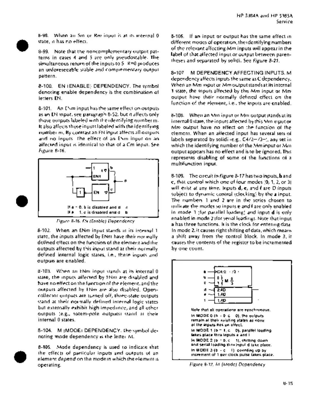
8-109.
The circuit
in
Figure 8-17
has
two
inputs,
band
c, that control
which
one
of
four
modes
(0,
1,
2,
or
3)
will exist at any time. Inputs d,
e,
and f are D inputs
subject
to
dynamic
control
(clocking) by the a
input.
The numbers 1 and 2 are in the series chosen
to
indicate the modes
so
inputs e and
fare
only
enabled
in
mode
1 (for parallel loading) and
input
d
is
only
enabled in
mode
2 (for serial loading). Note
that
input
a
has
three functions. It
is
the clock
for
entering data.
In
mode
2,
it
causes
right
shifting
of
data,
which
means
a shift away
from
the
control
block. In
mode
3,
it
causes
the
contents
of
the register
to
be incremented
by
one
count.
a
-I>C4/2-
/3
+
b-
0}
0
c-J
MJ
d-
2,4D
e-
1,4D
f-
1,4D
_
...
-
Note
that
all
operations
are
synchronous.
In
MODE
0
(b
=
0,
c = 0),
the
outputs
remain at
their
existing
states as
none
of
the
inputs
has an effect.
In
MODE
1
(b
= 1, c = 0), parallel
loading
takes place
thru
inputs
e and f.
In
MODE
2
(b
= 0, c = 1),
shifting
down
and serial
loading
thru
input
d take place.
In
MODE
3
(b
= c = 1),
counting
up
by
increment
of
1
per
clock
pulse takes place.
Figure
8-17.
M
(Mode)
Dependency
8-15