HP
5384A
and
HP 5385A
Service
8-110. M
DEPENDENCY
AFFECTING OUTPUTS.
When
an Mm
input
or
Mm
output
stands at its in-ternal
1 state,
the
affected
outputs
stand
at
their
normally
defined
internal logic states, i.e.,
the
outputs
are
enabled.
8-111.
When
an
Mm
input
or
Mm
output
stands at
its
internal 0 state,
at
each
affected
output
any
set
of
labels
containing
the
identifying
number
of
that
Mm
input
or
Mm
output
has
no
effect
and
is
to
be
ignored.
When
an
output
has several
different
sets
of
labels
separated
by solidi (e.g.,
2,
413, 5), only
those
sets in
which
the
identifying
number
of
this Mm
input
or
Mm
output
appears
are
to
be
ignored.
8-112.
In
Figure 8-18,
mode
1 exits
when
the
a
input
stands
at
its internal 1 state. The
delayed
output
symbol
is
effective
only
in
mode
1
(when
input
a=
1)
in
which case
the
device
functions as a
pulse-triggered
flip~flop.
See
paragraphs
8-125
through
8-129.
When
input
a=
0,
the
device
is
not
in
mode
1 so
the
delayed
output
symbol has
no
effect
and
the
device
functions
as a
transparent
latch.
a=ra--1
b C2
11
d
c
20
Figure 8-18. Type
of
Flip-i=lop
Determined
by
Mode
8-113.
In
Figure 8-19,
if
input
a stands at its
internal1
state establishing
mode
1,
outupt
b will
stand
at
its
internal 1 state
only
when
the
content
of
the
register
equal
9.
Since
output
b
is
located
in
the
common-
control
block with
no
defined
function
outside
of
mode
1, this
output
will
stand
at
its
internal 0
state
when
input
a stands
at
its internal 0 state, regardless
of
the
register
content.
8-16
a~b
I I
I I
I I
?
~
Figure 8-19. Disabling an
Output
of
the
Common
Control
Block
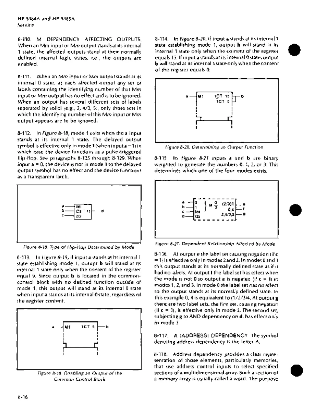
8-114.
In
Figure 8-20,
if
input
a stands at its
internal1
state establishing
mode
1,
output
b will
stand
at
its
internal 1 state only
when
the
content
of
the
register
equals
15. If
input
a stands
at
its internal 0 state,
output
b
will
stand at its
internal1
state only
when
the
content
of
the
register
equals
0.
a~b
I 1CT=O
t-J
I I
I I
~
s
Figure 8-20.
Determining
an
Output
Function
8-115.
In
Figure
8-21
in puts a
and
b
are
binary
weighted
to
generate
the
numbers
0, 1, 2,
or
3. This
determines
which
one
of
the
four
modes
exists.
a~--}~~-
~2;;)~~
e
b 1 3
04
f
c
N4
'
d GS
2,4/3,5
g
--------
Figure 8-21.
Dependent
Relationship
Affected
by
Mode
8-116. At
output
e
the
label
set
causing
negation
(if
c
=
1)
is
effective only in
modes2and
3.1n
modesOand
1
this
output
stands at its normally
defined
state
as
if
it
had
no
labels. At
output
f
the
label
set
has effect
when
the
mode
is
not
0
so
output
e
is
negated
(if
c =
1)
in
modes
1,
2,
and
3.
In
mode
0
the
label set has
no
effect
so
the
output
stands
at its normally
defined
state.
In
this
example
0,
4
is
equivalent
to
(1/2/3)4. At
output
g
there
are
two
label sets.
the
first set, causing
negation
(if
c = 1),
is
effective only in
mode
2.
The
second
set,
subjecting
g
to
AND
dependency
on
d,
has effect
only
in
mode
3.
8-117. A (ADDRESS) DEPENDENCY. The symbol
denoting
address
dependency
is
the
letter
A.
8-118. Address
dependency
provides
a
clear
repre-
sentation
of
those
elements,
particularly
memories,
that
use
address
control
inputs
to
select specified
sections
of
a multidimensional array. Such a
section
of
a
memory
array
is
usually called a
word.
The
purpose
•
•
•