Automating Measurements
Controlling Peripherals
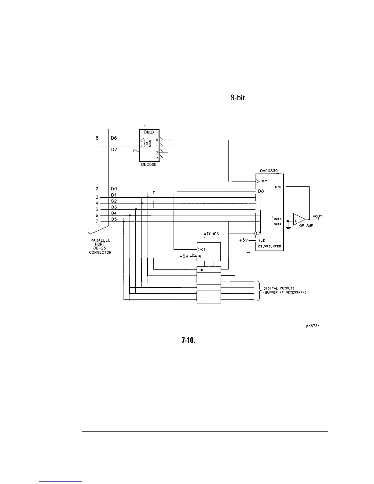
The data will typically remain valid until the next write to the parallel port,
but you should always latch the data using the strobe. Figure 7-10 shows a
simple circuit which can be used to write to an
8-bit
DAC and a digital latch.
s
139
DMIJX
0
D6
9
D7
“STROBE
3:
1
h
g-
31
DECODE
DO
nr
T
DAC0830
+=--I
,
-
40
PARALLEL
PORT
08-25
CONNECTOR
‘I
I
I I
I
LATCHES
D7
s
174
+5v--
ILE
---
>Cl
CS.VR2.XFER
+5vA
R
7
jl
+
OP
AMP
-I
“OUT
-
NOTE: ESD PROTECTION, POWER SUPPLIES AND DECOUPLING ARE NOT SHOWN.
Figure
7-10.
Digital latch Circuit
7-58
深圳市盛腾仪器仪表有限公司 Tel:0755-83589391 Fax:0755-83539691 Website: www.Sengt.com

 Loading...


