12
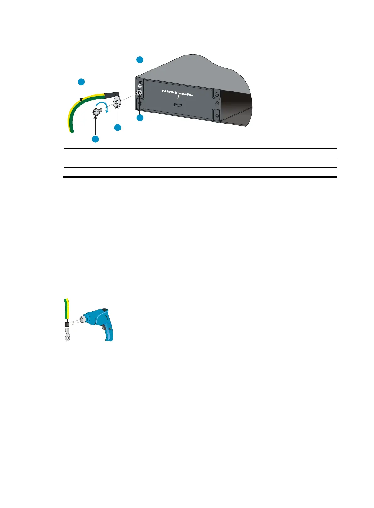
Figure 11 Connecting the grounding cable to the chassis
(1) Groundin
cable (2) Groundin
si
n
(3) Grounding hole (4) OT terminal
(5) Groundin
screw
4. Check that the grounding cable has been securely connected to the rear grounding point.
5. Remove the hex nut of a grounding post on the grounding strip.
6. Cut the grounding cable as appropriate for connecting to the grounding strip.
7. Peel 5 mm (0.20 in) of insulation sheath by using a wire stripper, and insert the bare metal part
through the black insulation covering into the end of the OT terminal supplied with the switch.
8. Secure the metal part of the cable to the OT terminal with a crimper, cover the joint with the
insulation covering, and heat the insulation covering with a blow dryer to completely cover the
metal part.
9. Connect the OT terminal to the grounding post of the grounding strip, and fasten it with the
removed hex nut.
Figure 12 Attaching an OT terminal to the grounding cable
1
2
3
4
5

 Loading...


