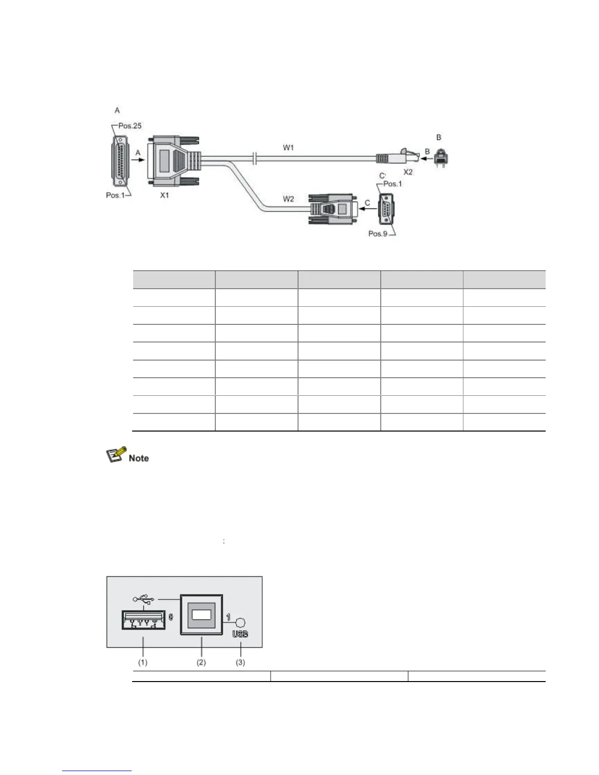
25 (male) connector, of which you can select one to the serial
AUX cable connector pinouts
For the connection of the AUX cable, refer to “Connecting the AUX Port to a Modem” in Chapter
4 “Installing the Router.”
USB interfaces
Universal serial bus (USB) interfaces can connect multiple types of devices and provide a
higher data transfer rate than common parallel interfaces and serial interfaces.
The device fully supports USB 1.1. The USB interfaces of the device allow for conven
storage.
Figure 1-13 USB interfaces
(1) USB interface 0
1) USB interface 0
25 (male) connector, of which you can select one to the serial
AUX cable connector pinouts
Signal direction DB-25 pin DB-
For the connection of the AUX cable, refer to “Connecting the AUX Port to a Modem” in Chapter
Universal serial bus (USB) interfaces can connect multiple types of devices and provide a
higher data transfer rate than common parallel interfaces and serial interfaces.
The device fully supports USB 1.1. The USB interfaces of the device allow for conven
Signal
RTS
DTR
TXD
DCD
GND
RXD
DSR
CTS
For the connection of the AUX cable, refer to “Connecting the AUX Port to a Modem” in Chapter
Universal serial bus (USB) interfaces can connect multiple types of devices and provide a
higher data transfer rate than common parallel interfaces and serial interfaces.
The device fully supports USB 1.1. The USB interfaces of the device allow for conven