Item Description
DC power input terminals (DC-powered) Provides –48 VDC to –60 VDC
PGND terminal
Connected to the ground through a PGND cable. For the
connection of the grounding terminal, refer to “PGND Cable
Connection” on page 4-7.
Connecting the AC Power Cord
AC power supply
Rated voltage range: 100 VAC to 240 VAC; 50 Hz to 60 Hz.
AC power socket
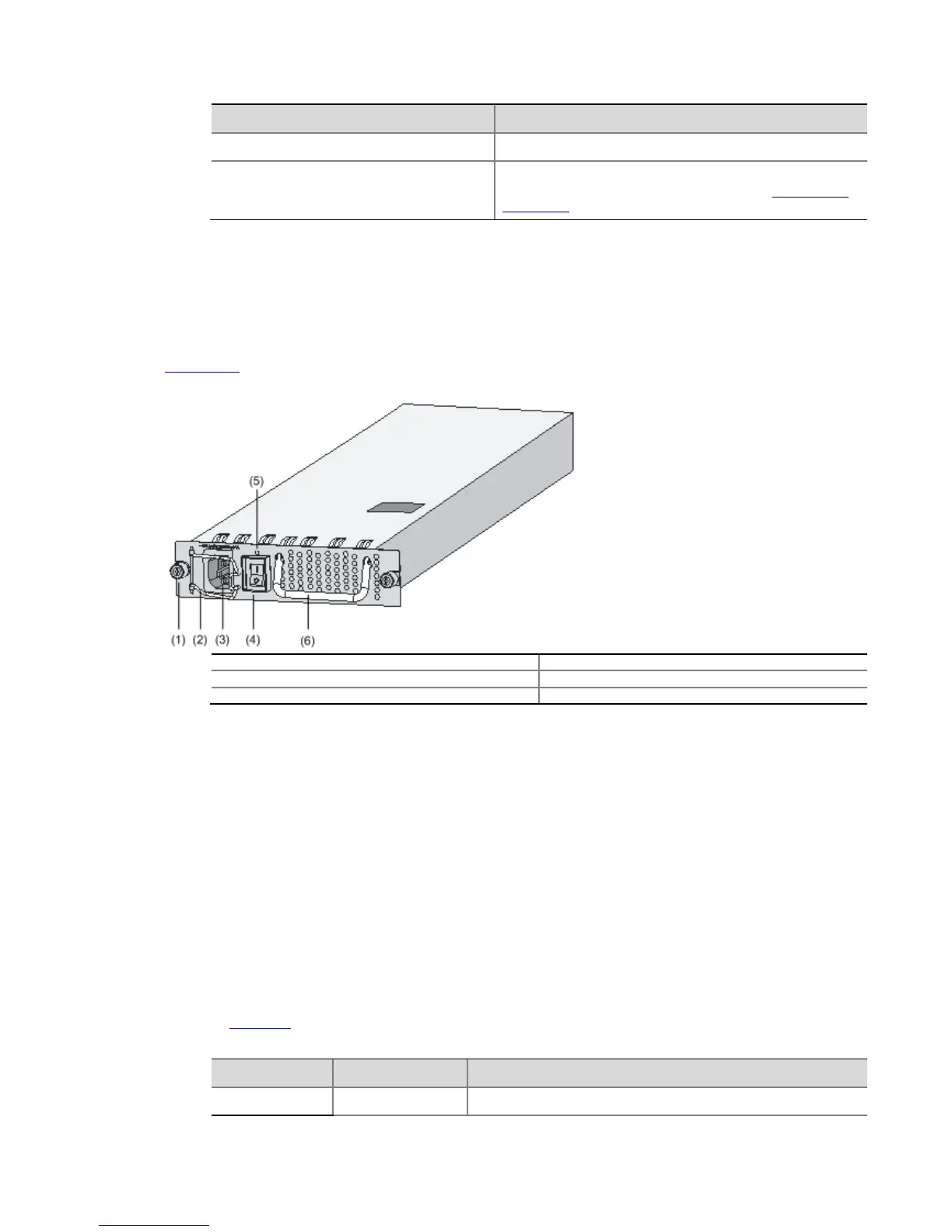
Figure 4-42 illustrates an AC power module in the chassis.
Figure 4-42 AC power module in a chassis
(1) Captive screw (2) Bail latch holder
(3) AC power socket (4) Power switch
(5) Power LED (6) Power module handle
Use a three-terminal, single-phase power connector with a grounding contact.
Ground the power supply reliably. Normally, the grounding contact of the power supply system
in a building was buried during construction and cabling.
Before connecting the AC power cord, make sure that the power supply of the building is well
grounded.
Connection procedure
Follow these steps to connect the AC power cord:
Step1 Make sure that the PGND terminal is securely connected to the ground.
Step2 Move the AC power switch on the power modules to the OFF position.
Step3 Move the bail latch to the left.
Step4 Connect one end of the supplied AC power cord to the power socket on the router, and the
other end to an AC power outlet.
Step5 Move the bail latch to the right to hold the power cord in position.
Step6 Move the power switches on all power modules to the ON position.
Step7 Check the status of the PWR LED on the front panel of the router. For the status of the power
LED, see Table 4-5.
Table 4-5 Status of the power LED
LED Color Status
Power LED
Solid green The power module works normally.