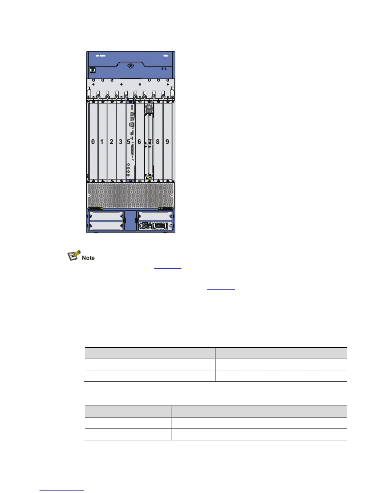
Figure 2-2 Slot arrangement on the A6616 configured with an RSE-X1
The numbers 0 through 9 in Figure 2-1 respectively represent Slot 0 through Slot 9 on the
A6616 configured with an RPE-X1. Actually, these numbers are not silk-screened on the
router.
The numbers 0 through 3 and 5 through 9 in Figure 2-2 respectively represent Slot 0
through Slot 3 and Slot 5 through Slot 9 on the A6616 configured with an RSE-X1. Note
that no slot is named Slot 4 on the A6616 when it is configured with the RSE-X1.
Slot Arrangement for MPUs and FIPs
Table 2-1 Slot arrangement for MPUs
MPU Slot arrangement
RPE-X1 (supporting 1+1 redundancy) Slot 4 and Slot 5
RSE-X1 (supporting 1+1 redundancy) Slot 5 and Slot 6
Table 2-2 Slot arrangement for FIPs
FIP Slot arrangement
FIP-100 Slot 0 through Slot 3, Slot 6 through Slot 9
FIP-110 Slot 0 through Slot 3, Slot 6 through Slot 9