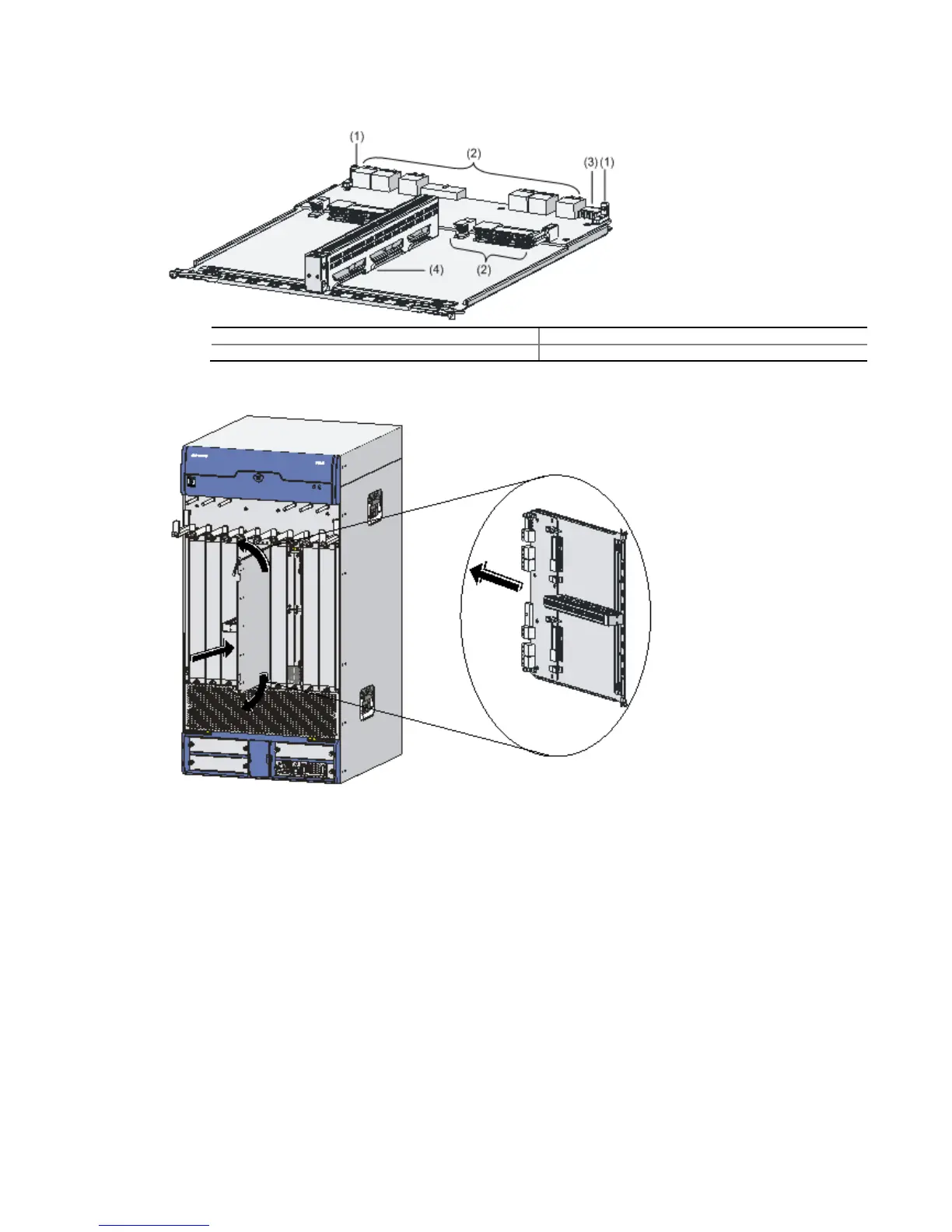
Figure 4-10 Structure of the chassis accessory
(1) Positioning holes (2) Bus connectors
(3) Power connector (4) Slide rail
Figure 4-11 Install a chassis accessory
Step4 Gently push the chassis accessory (with the components facing left) into Slot 4 or Slot 5 along
the slide rails until the positioning pins on the backplane are seated in the positioning holes at
the bottom of the chassis accessory. Then push the ejector levers inward to lock the chassis
accessory in position and fasten the captive screws on the ejector levers.
Step5 Gently push the RPE-X1 into Slot 5 along the slide rails, and then push the ejector levers
inward to lock the board in position.