EasyManuals Logo

HP dc5100 - Microtower PC Service & Reference Guide

HP dc5100 - Microtower PC
230 pages
To Next Page IconTo Next Page
To Previous Page IconTo Previous Page
Page #146 background imageLoading...
Page #146 background image
7–34 376220-001 Service Reference Guide, dc5100
Removal and Replacement Procedures— Small Form Factor (SFF) Chassis
7.12 Power Switch Assembly
1. Prepare the computer for disassembly (Section 7.1, “Preparation for Disassembly”).
2. Remove the computer cover (Section 7.4, “Computer Cover”).
3. Disconnect the power switch/LED cable from the system board.
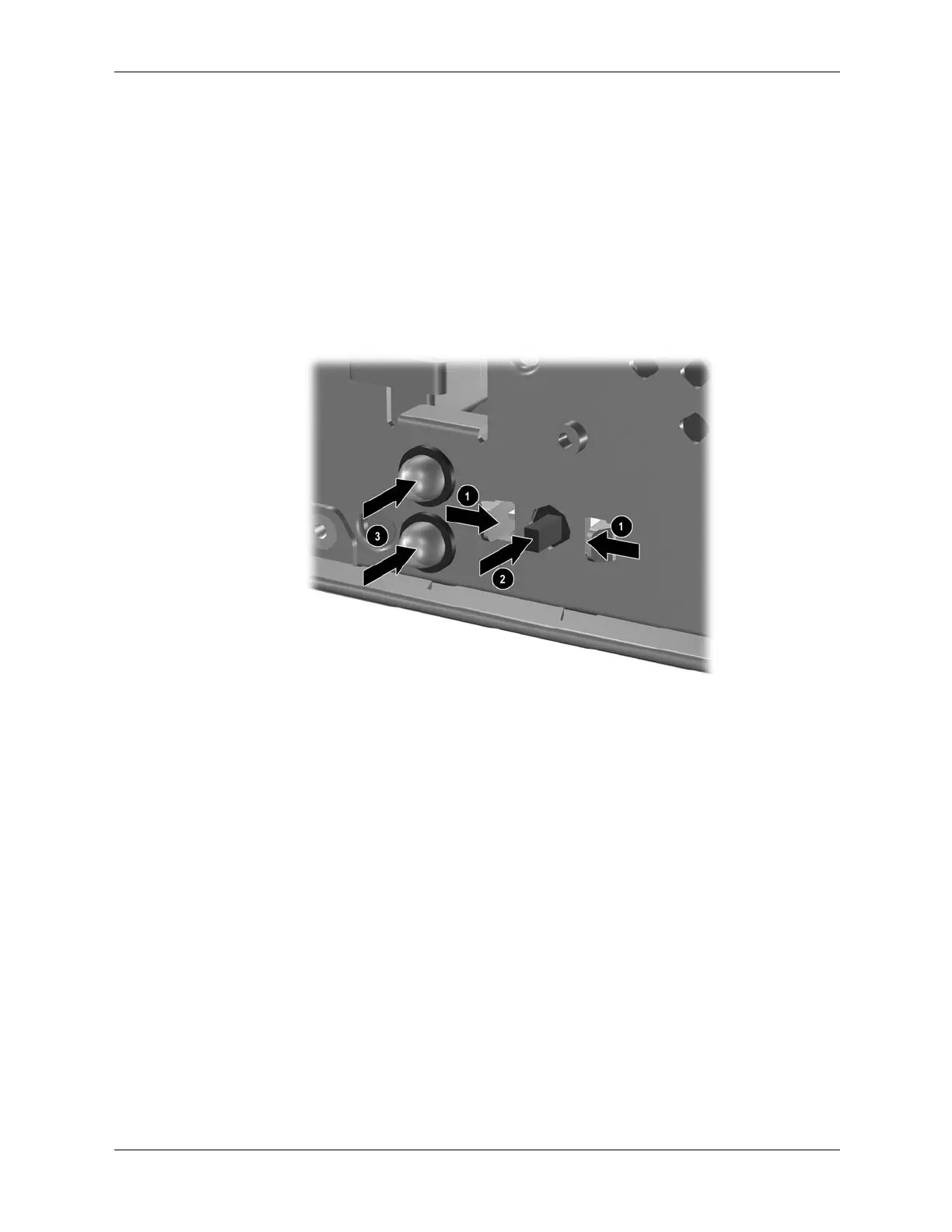
4. Squeeze the switch holder retaining clips together at the front of the chassis 1 and push the
switch assembly out of the chassis 2. Push the two LEDs out of the chassis 3.
5. If necessary, the LED holders may also be removed by squeezing the clips and pushing them
out of the front of the chassis 4.
To install the power switch and LEDs, reverse the removal procedure.

Table of Contents

Other manuals for HP dc5100 - Microtower PC

Questions and Answers:

Question and Answer IconNeed help?

Do you have a question about the HP dc5100 - Microtower PC and is the answer not in the manual?

HP dc5100 - Microtower PC Specifications

General IconGeneral
ProcessorIntel Pentium 4 or Intel Celeron D
MemoryUp to 4 GB DDR2 SDRAM
NetworkIntegrated Broadcom NetXtreme Gigabit Ethernet
Operating SystemWindows XP Professional
Optical DriveDVD-ROM, CD-RW, or DVD+/-RW
GraphicsIntel Graphics Media Accelerator 900
AudioIntegrated audio
Expansion Slots1 PCI Express x16, 3 PCI
Ports1 Serial, 1 Parallel
WeightApprox. 22 lbs (10 kg)
Processor SpeedUp to 3.8 GHz
Storage40 GB to 250 GB HDD

Related product manuals