System Overview
2–3
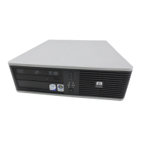
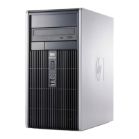
System Front View
Figure 2–1 is a front view of the system showing the location of the controls and
indicators. Table 2–1 describes these items.
1 2 3 4
567
Figure 2–1: Front View of System
Table 2–1: Front Components
Figure
Legend
Control or Indicator Function
1 Floppy drive (optional) Location of 3.5-inch drive bay.
2 Floppy eject button Ejects floppy diskette when pushed.
3 CD-ROM drive 5.25-inch half-height front-accessible drive
bay.
4 CD-ROM eject button Opens the CD loading drawer.
5 Reset button This button resets the system and causes the
self-test to run.
6 Power indicator Lights when the system is on.
7 Disk activity indicator Lights when a hard disk drive on the
embedded SCSI controller bus is in use.
 Loading...