System Overview
2–4
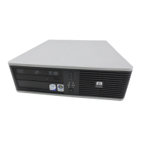
System Rear View
Figure 2–2 shows the rear connectors and lock. Table 2–2 lists the rear connectors and lock
and describes their functions.
1
2
3
4
5
6
7
8
10
11
12
13
14151617182021
9
1
2
19
Figure 2–2: Rear Connectors
Table 2–2: Rear Connectors
Figure
Legend
Connector Function
1 Power on/off switch Turns AC power on or off.
2 Key lock Locking mechanism for system cover.
3 MAU Media adapter unit (optional).
4 Enhanced bidirectional
parallel port
Connects an industry-standard parallel printer or
other parallel device.
 Loading...