Power Switch/LED Assembly
1. Prepare the computer for disassembly (Preparation for Disassembly on page 29).
2. Remove the access panel (
Access Panel on page 30).
3. Lay the computer on its side with the front facing toward you.
4. Remove the front bezel (
Front Bezel on page 31).
5. Remove the optical drive (
Removing an Optical Drive on page 46).
6. Disconnect the braided cables from the black system board connector labeled JFP1.
7. Remove the cable from the clips in the optical drive cage.
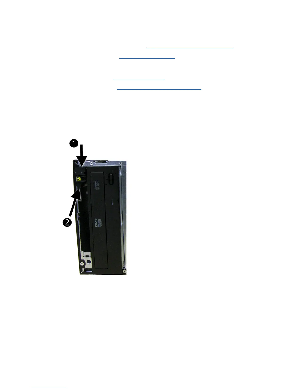
8. Press the tab on the top of the switch holder (1) to disengage it from the chassis, lift the switch
upward (2) to disengage the tab at the bottom of the switch from the chassis, and then pull the
power switch away from the chassis while guiding the wires through the hole in the chassis.
To install the power switch/LED assembly, reverse the removal procedures.
58 Chapter 7 Removal and Replacement Procedures Microtower (MT) Chassis
 Loading...