NOTE: You can break the connection between any disk enclosures in the main rack except
for disk enclosures that are connected to the controllers. The break shown in Figure 11
(page 14) is just one example.
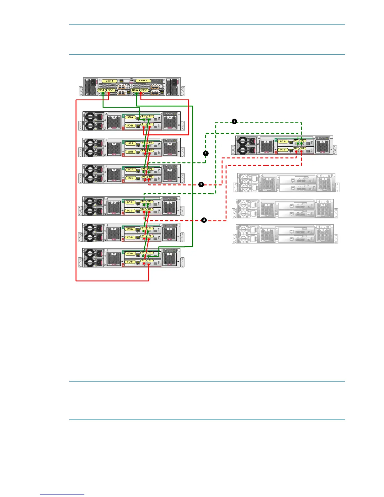
Figure 11 Connecting one expansion rack disk enclosure to the P6300 EVA 2C6D main rack
4. Using one of the 6m cables from the expansion kit, connect P2 (I/O-A) on the disk enclosure
in the top group in the main rack to P1 (I/O-A) on the top disk enclosure in the expansion
rack (1, Figure 11).
5. Using one of the 6m cables from the expansion kit, connect P1 (I/O-A) on the disk enclosure
in the bottom group in the main rack to P2 (I/O-A) on the top disk enclosure in the expansion
rack (2, Figure 11).
In Step 4 and Step 5, I/O module A is cabled first. However either I/O module can be
connected first as long as the other I/O module ports (in this example, B) in the main rack
disk enclosure are not unplugged until cabling is complete on the first I/O module and you
have completed Step 6.
NOTE: With only one I/O module from the newly added enclosure cabled to the array in
the main rack, there will be HP P6000 Command View warnings that indicate disk drives in
the system are only connected on one of the redundant loops. This is to be expected, and the
warnings should clear as soon as the other I/O module is connected.
6. Once you connect one I/O module (for example, A), verify the status of the I/O module A
ports and the presence of the newly added disk enclosures before you connect the other I/O
modules (in this example, B). Failure to complete this verification could result in potential loss
of data access for an extended period of time. Complete the following steps to verify:
a. Open HP P6000 Command View.
14 Connecting the main rack to the expansion rack

 Loading...