Chapter 1
HP Integrity rx8640 and HP 9000 rp8440 Server Overview
Detailed Server Description
27
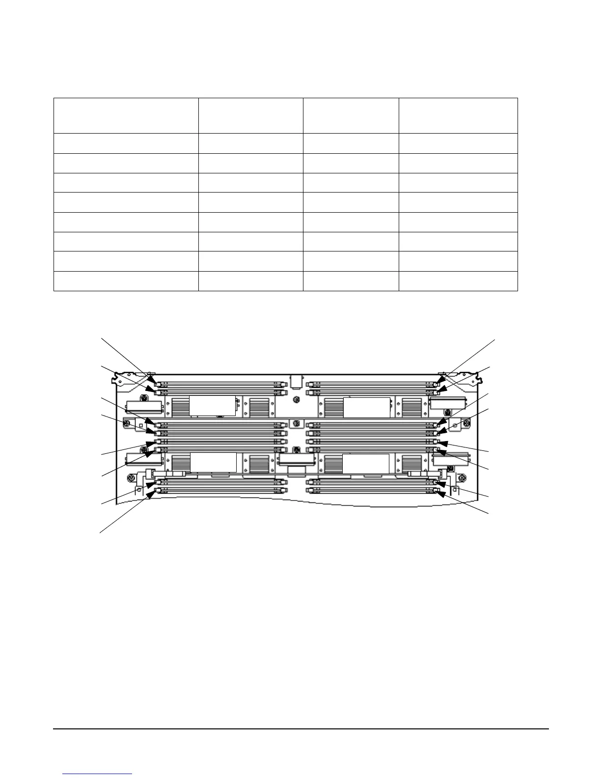
Figure 1-9 DIMM Slot Layout
Cells and nPartitions
An nPartition comprises one or more cells working as a single system. Any I/O chassis that is attached to a
cell belonging to an nPartition is also assigned to the nPartition. Each I/O chassis has PCI card slots, I/O
cards, attached devices, and a core I/O card assigned to the I/O chassis.
Table 1-3 DIMM Load Order
Number of DIMMs
Installed
Action Taken
DIMM Location
on Cell Board
Quad Location
2 DIMMs = 1 rank Install first 0A and 0B Quad 2
4 DIMMs = 2 rank Add second 1A and 1B Quad 1
6 DIMMs = 3 rank Add third 2A and 2B Quad 3
8 DIMMs = 4 rank Add fourth 3A and 3B Quad 0
10 DIMMs = 5 rank Add fifth 4A and 4B Quad 2
12 DIMMs = 6 rank Add sixth 5A and 5B Quad 1
14 DIMMs = 7 rank Add seventh 6A and 6B Quad 3
16 DIMMs = 8 rank Add last 7A and 7B Quad 0
Rear Edge of Cell Board
Front Edge of Cell Board
(Plugs into Server Backplane)
Quad 1
Quad 0Quad 2
Quad 3
1A
1B
5B
5A
7A
7B
3B
3A
6A
6B
2B
0A
4B
4A
2A
0B
 Loading...


