2-26
Installing the Switch
Installation Procedures
If you want to continue with console management of the switch at this time,
see chapter 3, “Getting Started With Switch Configuration” for some basic
configuration steps. For more detailed information, refer to the Management
and Configuration Guide, which is on the ProCurve Website at www.hp.com/
go/procurve/manuals.
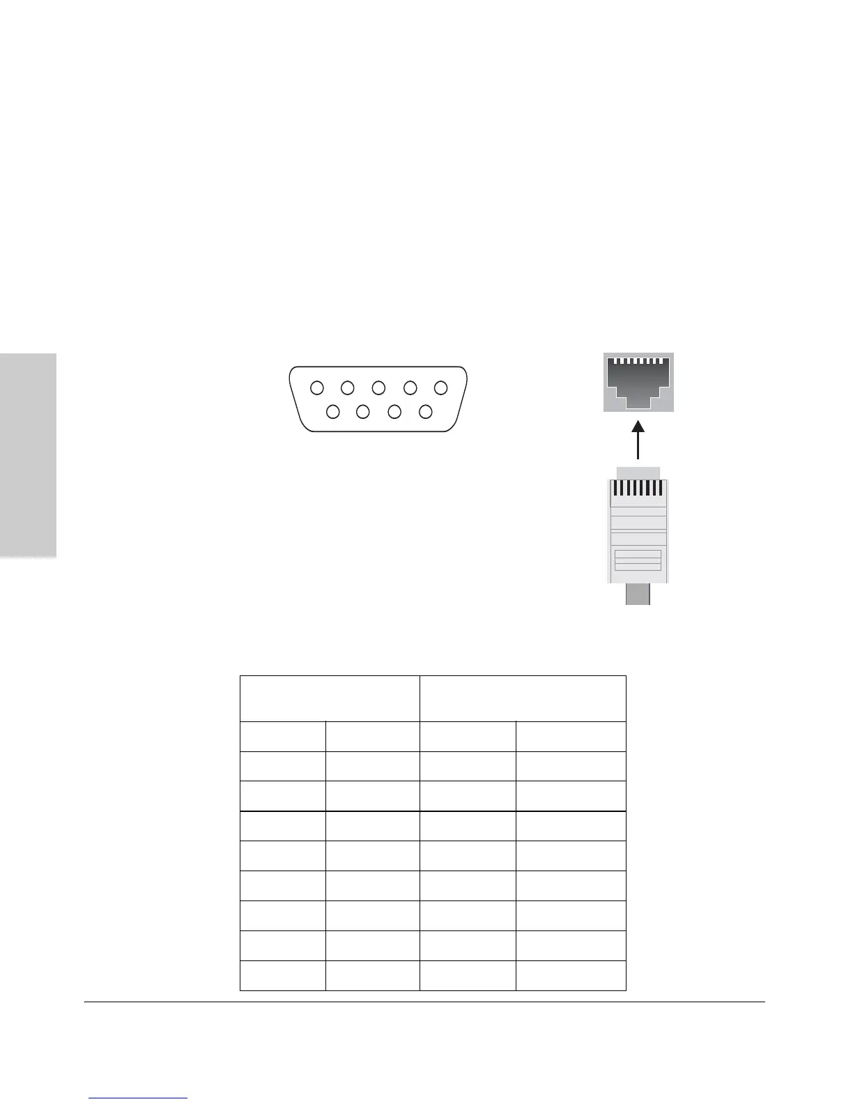
Console Cable Pinouts
The console cable has an RJ-45 plug on one end and a DB-9 female connector
on the other end. Table 2-19 describes the mapping of the RJ-45 to DB-9 pins.
Figure 2-20. RJ-45 to DB-9 pinouts
Table 2-3. Mapping of RJ-45 to DB-9
RJ-45 (Signal reference from
Chassis
DB-9 (Signal reference from PC)
Reserved18CTS
Reserved 2 6 DSR
TXD 3 2 RXD
Reserved 4 1 DCD
GND 5 5 GND
RXD 6 3 TXD
Reserved 7 4 DTR
Reserved87RTS
9RI
 Loading...