34 Installing the enclosures
2. Plug the power cord into the power cord connector on the back of the drive enclosure (see Figure 11).
Plug the other end of the power cord into the rack power source. Wait several seconds to allow the
disks to spin up.
Repeat this sequence for each PSU within each drive enclosure.
3. Plug the power cord into the power cord connector on the back of the controller enclosure (see
Figure 11). Plug the other end of the power cord into the rack power source.
Repeat the sequence for the controller enclosure’s other PSU.
To power off the system:
1. Stop all I/O from hosts to the system.
2. Shut down both controllers using either method described below:
• Use SMU to shut down both controllers, as described in the online help and web-posted HP
P2000G3MSA System SMU Reference Guide.
Proceed to step 3.
• Use the command-line interface (CLI) to shut down both controllers, as described in the HP
P2000G3MSA System CLI Reference Guide.
3. Disconnect the power cord’s male plug from the power source.
4. Disconnect the power cord’s female plug from the power cord connector on the PSU.
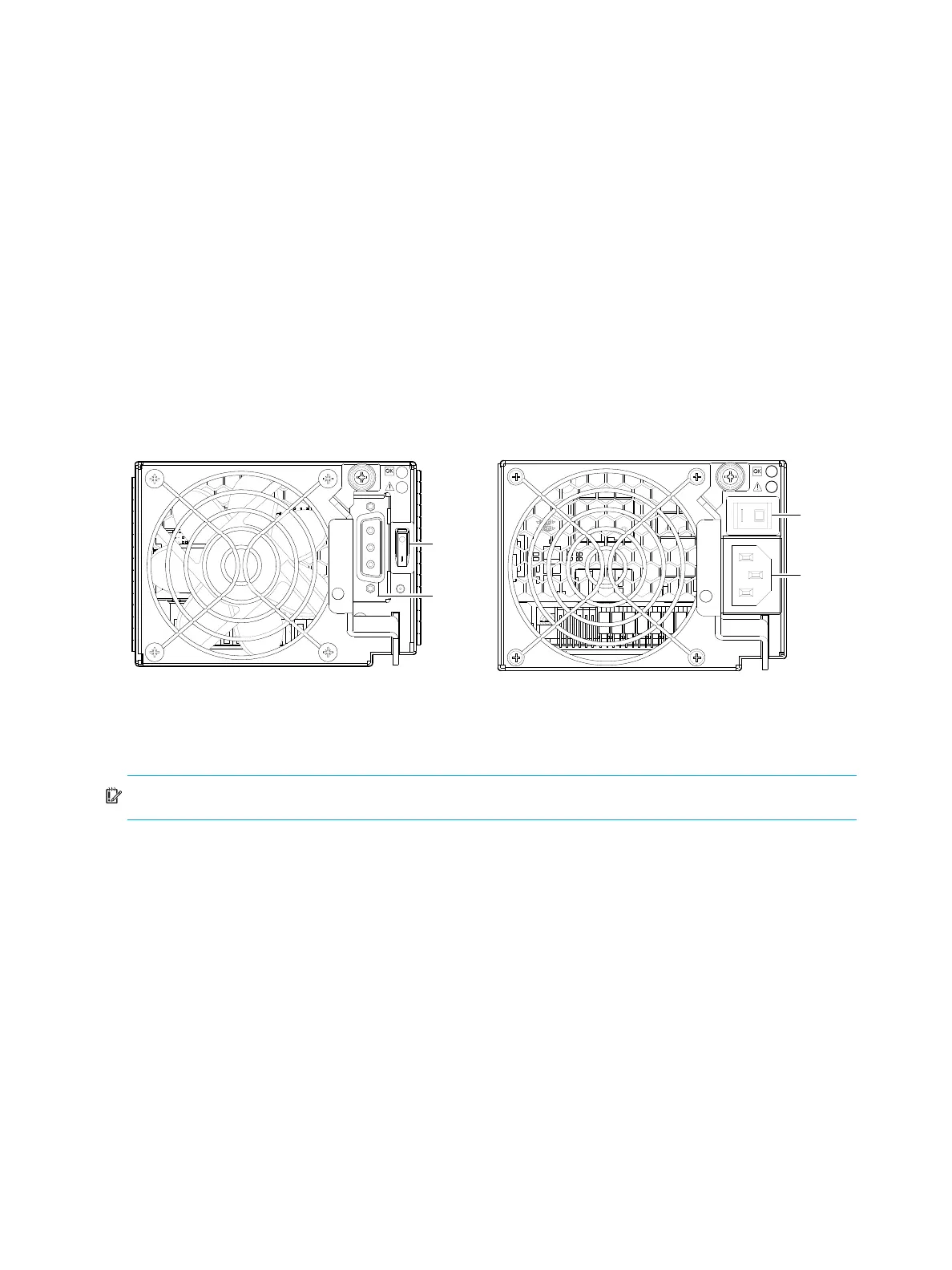
Figure 12 DC PSU and AC PSU with power switch
Power Cords
IMPORTANT: See Environmental requirements and specifications for additional information.
AC model
Obtain two suitable AC power cords: one for each AC PSU that will connect to a separate power source.
See the illustration at right (in Figure 12 on page 34) when performing the following steps:
1. Verify that the enclosure’s power switches are in the Off position.
2. Identify the power cord connector on the PSU, and locate the target power source.
3. For each PSU, perform the following actions:
a. Plug one end of the cord into the power cord connector on the PSU.
b. Plug the other end of the power cord into the rack power source.
4. Verify connection of primary power cords from the rack to separate external power sources.
See Power cycle on page 35.
Power
switch
Power
cable
connect
Power
switch
Power
cord
connect
DC power supply unit Legacy AC power supply unit