2-19
Installing the 5400zl Switches
Installation Procedures
Installing the 5400zl
Switches
2. Crimp the grounding lug to a properly grounded grounding wire.
3. Re-attach the grounding lug to the switch with the two screws.
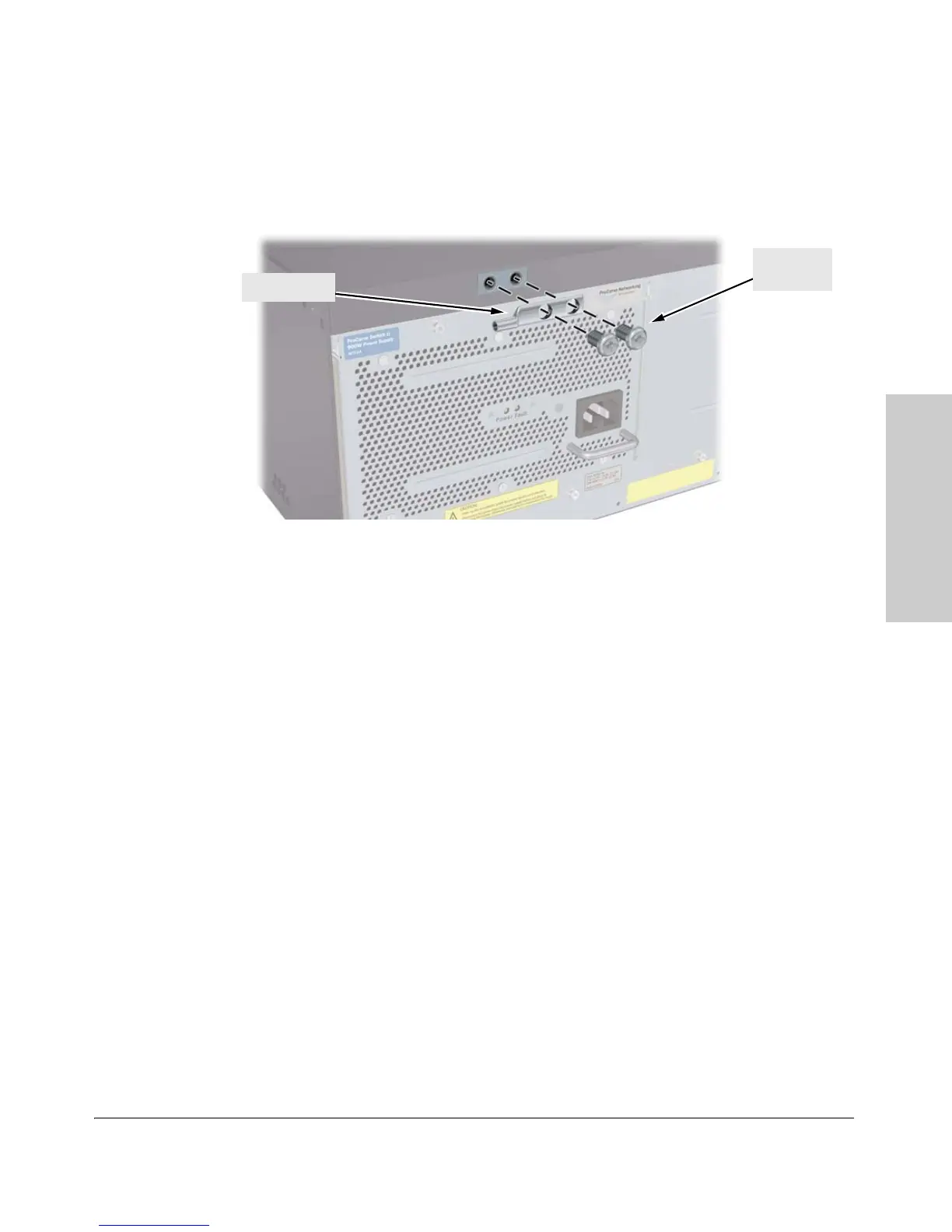
Figure 2-10. Attaching Grounding Lug to the 5400zl Switch
7. Connect the Switch to a Power Source
1. Plug the included power cord into the switch’s power connector and into
a nearby properly grounded AC power source.
If a redundant power source is available, it is desirable to power one
switch power supply from the regular AC source, and the other power
supply from the redundant AC source. This will provide redundancy in AC
power to the switch, as long as the switch PoE power usage falls within
the capability of one power supply. If both power supplies are plugged
into a common AC source, there is still power supply redundancy, that is,
protection against power supply failure, but if the AC source fails, the
switch will lose all power.
2. Re-check the LEDs during self test. See “LED Behavior” on page 2-14.
8. (Optional) Connect a Power Supply Shelf
to the switch
1. Connect the supplied external power supply (EPS) cables to the switch
and to the Power Supply Shelf.
2. Tighten the thumb screws on all connectors to prevent any accidental
disconnects.
3. Plug the power supply cords into the power connector and into a nearby
properly grounded AC power source.
Grounding lug
Grounding
lug screws

 Loading...