2-22
Installing the 5400zl Switches
Installation Procedures
Installing the 5400zl
Switches
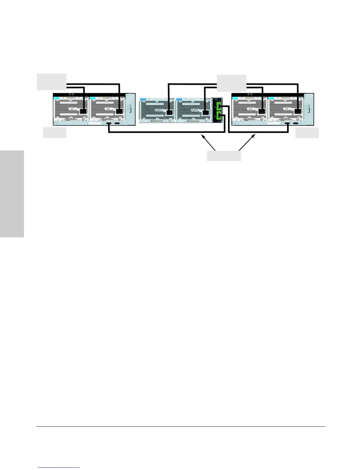
Figure 2-12. Connecting the EPS to two 5406zl switches
Although these examples show the EPS connecting to the 5406zl switch, it can
also be connected to a 5412zl switch in the same manner. These examples also
show the switch and the EPS using the J8713A power supply, the J8712A
power supply can also be used. It depends on how much PoE power is
required.
For more information on PoE requirements see the PoE (Power over
Ethernet) Devices Planning and Implementation Guide.
9. Connect the Network Devices
The type of network connections you will need to use depends on the types
of switch modules you have installed in your 5400zl switch. See the documen
-
tation accompanying the modules for cabling configurations and procedures
for those modules.
In general for all the modules, when a network cable from an active network
device is connected to the switch, the Link LED for the switch port should go
on. If the Link LED does not go on, use the table below to help solve the
problem, and see the module documentation for troubleshooting procedures.
EPS Cables
5406zl
5406zl
To Powe r
Source
To P o we r
Source

 Loading...