Do you have a question about the HP ProLiant DL980 G7 and is the answer not in the manual?
Catalog listing mechanical parts with diagrams and spare part numbers for identification.
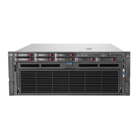
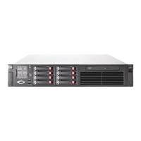
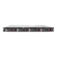
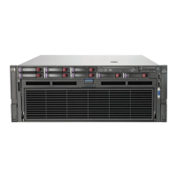
Identification and listing of various system components and their associated part numbers.
Lists the necessary tools for performing server maintenance and replacement tasks.
General safety guidelines and warnings to be followed before servicing the server.
Precautions to prevent damage from static electricity when handling server components.
Important warnings and cautions related to server installation and operation.
Step-by-step procedure to safely shut down the server before maintenance.
Procedure for removing and replacing hot-plug power supply units.
Procedures for removing and replacing server fan modules.
Steps to remove the processor memory drawer and its blank.
Procedure for removing and replacing memory cartridges.
Procedure for removing and installing individual Dynamic Random Access Memory modules.
Guidelines for correctly installing DIMMs to ensure proper recognition and performance.
Strategies for achieving optimal server memory performance through configuration.
Details on Advanced Memory Protection (AMP) modes like ECC, Online Spare, and Mirrored Memory.
Procedure for removing and replacing the processor heatsink assembly.
Procedure for removing and installing the server's central processing unit.
Procedure for removing and replacing solid state drive units.
Procedure for replacing the system's real-time clock battery.
Procedure for removing and replacing the main system motherboard.
Steps to re-enter serial and product IDs after system board replacement.
Procedure for removing and replacing the power backplane assembly.
Steps to upgrade the server from a 4-processor to an 8-processor configuration.
Prerequisites and supported hardware for system firmware updates.
Procedure for updating firmware using the Offline Update ISO method.
Procedure for updating firmware using Smart Components.
Steps for firmware updates using Smart Components on Windows/Linux.
Instructions for firmware updates on Solaris/VMware using Offline Update.
Identification of components located on the server's front panel.
Description and status interpretation of front panel LEDs.
Description and status interpretation of System Insight Display LEDs.
Identification and status interpretation of hard drive LEDs.
Interpretation of different hard drive LED status combinations for diagnosis.
Identification of components located on the server's rear panel.
Description and status interpretation of rear panel LEDs.
Description and status interpretation of power supply LEDs.
Identification and labeling of components on the system board.
Configuration and function of the system maintenance switch.
Identification of components on various expansion boards.
Description and status interpretation of battery pack LEDs.
Instructions for connecting XNC cabling, critical for 8-processor systems.
Instructions for connecting the DVD-ROM drive to the server.
Specifications for the server's operating environment (temperature, humidity, altitude, noise).
Technical specifications of the server, including dimensions, weight, and power requirements.
Glossary of acronyms and abbreviations used throughout the document.
Instructions on how to provide feedback to improve the documentation.