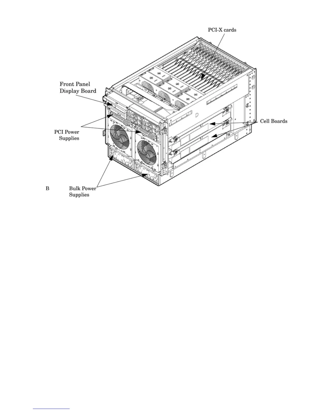
Figure 1-4 Right-Front View
Access the PCI-X card section, located toward the rear, by removing the top cover.
The PCI card bulkhead connectors are located at the rear top.
The PCI OLR fan modules are located in front of the PCI-X cards. These six 9.2-cm fans are housed
in plastic carriers. They are configured in two rows of three fans.
Four OLR system fan modules, externally attached to the chassis, are 15-cm (6.5-inch) fans. Two
fans are mounted on the front surface of the chassis and two are mounted on the rear surface.
The cell boards are accessed from the right side of the chassis behind a removable side cover.
The two MP/SCSI boards are positioned vertically at the rear of the chassis.
The two hot-pluggable N+1 redundant bulk power supplies provide a wide input voltage range.
They are installed in the front of the chassis, directly under the front fans.
A cable harness that connects from the rear of the BPSs to the system backplane provides DC
power distribution.
Access the system backplane by removing the left side cover. The system backplane hinges from
the lower edge and is anchored at the top with two jack screws.
The SCSI ribbon-cable assembly routes from the mass storage area to the backside of the system
backplane for connection to the MP/SCSI card, and to the AB290A LAN/SCSI PCI-X cards.
16 HP Integrity rx7640 Server and HP 9000 rp7440 Server Overview
 Loading...