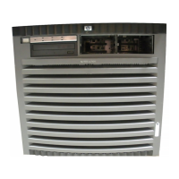
Figure 1-5 Left-Rear View
Front Panel
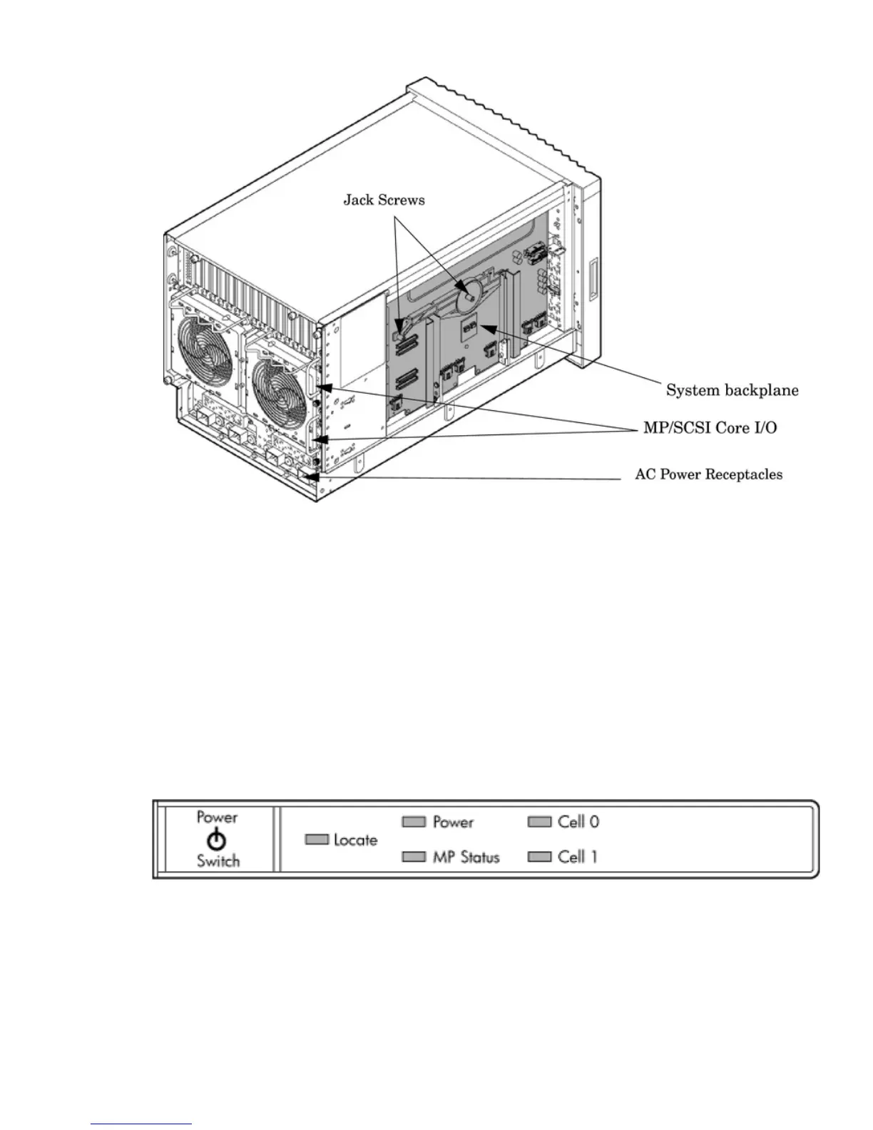
Front Panel Indicators and Controls
The front panel, located on the front of the server, includes the power switch. See Figure 1-6
Enclosure Status LEDs
The following status LEDs are on the front panel:
• Locate LED (blue)
• Power LED (tri-color)
• Management processor (MP) status LED (tri-color)
• Cell 0, 1 status (tri-color) LEDs
Figure 1-6 Front Panel LEDs and Power Switch
Cell Board
The cell board, illustrated in Figure 1-7, contains the processors, main memory, and the CC
application specific integrated circuit (ASIC) which interfaces the processors and memory with
the I/O, and to the other cell board in the server. The CC is the heart of the cell board, enabling
communication with the other cell board in the system. It connects to the processor dependent
hardware (PDH) and micro controller hardware. Each cell board holds up to two processor
modules and 16 memory DIMMs. One or two cell boards can be installed in the server. A cell
Detailed Server Description 17
 Loading...