Control panel and LED descriptions
Once the disk array is powered on and running normally, no user operations are required at the
control panel, except when you are instructed by your HP support representative.
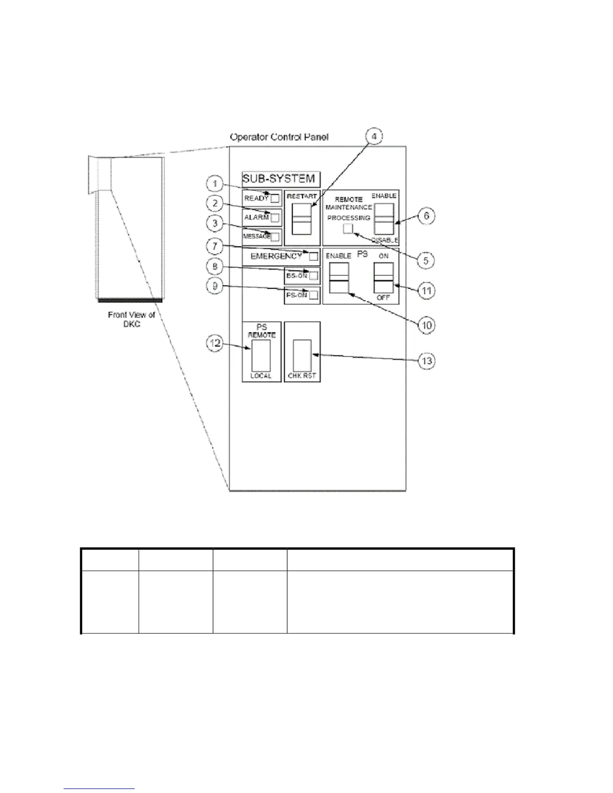
Figure 11 shows the control panel location and layout. Table 16 explains the control panel functions.
Figure 11 Control panel and LED descriptions
.
Table 16 Control panel control and LED descriptions
DescriptionIndicatorLabelItem
During normal operation, this LED should be on.
• ON: Input/output operation on the channel interface
is enabled.
• OFF: The system is not accepting data.
LED (Green)
SUB-SYSTEM
READY
1
Operating the HP XP24000/XP20000 Disk Array38