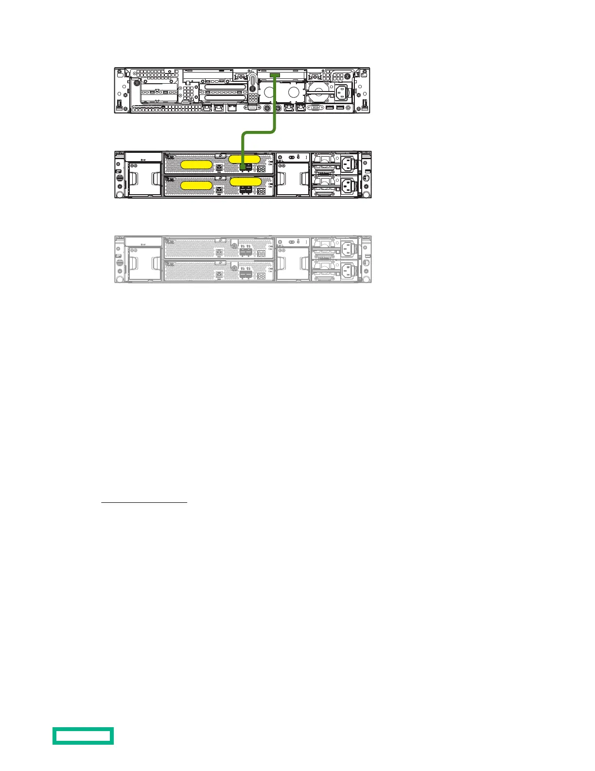
Figure 1: Server or controller enclosure to disk enclosure (single-domain)
Cabling guidelines–disk enclosure to disk enclosure
• To cascade additional disk enclosures from the disk enclosure that is connected to the server or controller enclosure,
use standard mini-SAS cables.
• As additional disk enclosures are connected to the first disk enclosure, they are assigned a box number. The assigned
box number is displayed on the 7-segment display on the rear of the disk enclosure.
• When connecting this disk enclosure in a single-domain environment, only the top I/O module (I/O module A) in the
disk enclosure is supported for use.
• The number of supported cascaded disk enclosures varies per disk enclosure model and installation environment. For
more information, see the QuickSpecs for the disk enclosure, controller, or controller enclosure, available on the
Accessing QuickSpecs website.
• Only use supported SAS cables with mini-SAS connectors.
• Use provided color clues on the disk enclosure when cabling cascaded disk enclosures; for example, connect “green”
ports to “green” ports (connect I/O module A on one disk enclosure to I/O module A on the additional disk enclosure).
• P1 on the disk enclosure I/O module is treated as the SAS “in” port.
• P2 on the disk enclosure I/O module is treated as the SAS “out” port.
• In single-domain configurations, one cable path is created between the host, the primary disk enclosure, and additional
cascaded disk enclosures.
• In dual-domain configurations, two cable paths are created between the host, the primary disk enclosure, and
additional cascaded disk enclosures.
Installing
18
 Loading...