Small Form Factor D37x0 disk enclosures — maximum capacity
configuration
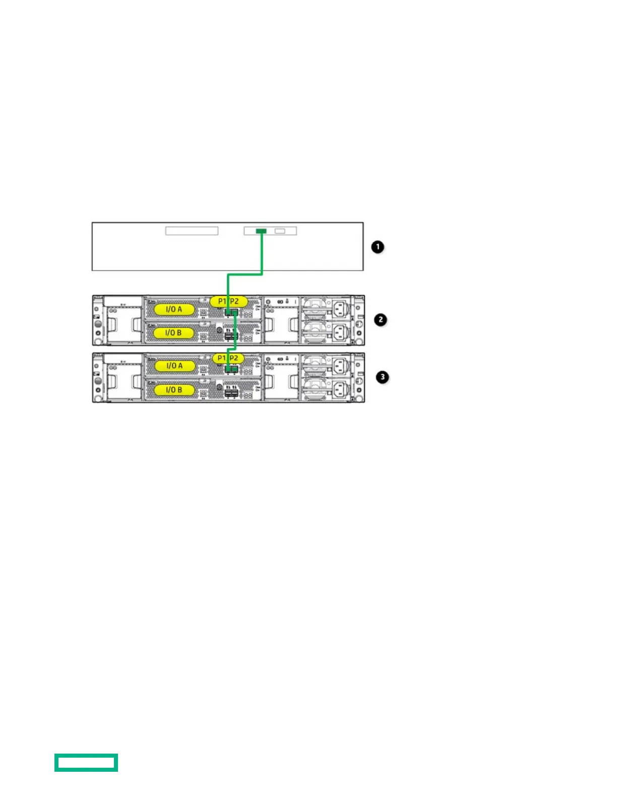
This example illustrates cabling for a single-domain configuration. In this configuration, note the following:
• P1 on the disk enclosure I/O module is treated as the SAS “in” port.
• P2 on the disk enclosure I/O module is treated as the SAS “out” port.
• In single-domain configurations, one cable path is created between the host, the primary disk enclosure, and additional
cascaded disk enclosures. (Shown)
• In dual-domain configurations, two cable paths are created between the host, the primary disk enclosure, and
additional cascaded disk enclosures.
1.
Host (server or controller enclosure)
2.
Primary disk enclosure
3.
Additional cascaded disk enclosure
Dual domain example — best fault tolerance cabling
This example illustrates cabling for a dual-domain configuration in a pattern that oers best possible fault tolerance. In
this configuration, note the following:
• A multi-port, dual-domain controller in the host and dual-port disk drives in the disk enclosure are required for dual-
domain deployments.
• Cables from each I/O module in the disk enclosure to the server or controller enclosure and to additional cascaded disk
enclosures provide dual-domain connectivity.
• The reversing of the cable paths ensures access to the storage, even if the controller, cable, enclosure I/O module, or
enclosure power supply fails.
This example illustrates using a disk enclosure with one additional cascaded disk enclosure. More than one additional disk
enclosure can be cascaded. For more information, see the QuickSpecs for the enclosure.
Cabling
23
 Loading...