Chapter 1: Component identification 7
Callout Item Description
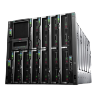
1 Quick access cover Provides access to internal components.
2 Locking cover latch Lock/unlock the quick access cover.
3 Power On/Standby button
and system power LED for
each server (1-4).
• Solid green = System on
• Flashing green (1 Hz/cycle per sec) = Performing power on
sequence
• Solid amber = System in standby
• Off = No power present
• Servers 1 and 2 are powered on/off by the buttons on the left side
of the chassis (server 1 is on the bottom). Servers 3 and 4 are
powered on/off by the buttons on the right side of the chassis.
NOTE:
Power LED off can indicate facility power is not present, power cord is
not attached, no power supplies are installed, power supply failure has
occurred, or the power button cable is disconnected because the server
is not installed.
4 Health LED for each server
(1-4)
• Solid green = Normal
• Flashing green (1 Hz/cycle per sec) = iLO is rebooting
• Flashing amber = System degraded
• Flashing red (1 Hz/cycle per sec) = System critical
NOTE:
If the Health LED indicates a degraded or critical state, review the
system IML or use iLO to review the system health status.
5 UID button/LED • Solid blue = Activated
• Flashing blue:
• ◦ 1 Hz/cycle per sec = Remote management or firmware upgrade
in progress.
◦ 4 Hz/cycle per sec = iLO manual reboot sequence initiated.
◦ 8 Hz/cycle per sec = iLO manual reboot sequence in progress.
6 Drives for servers 1-4 The chassis accomodates 2 to 4 servers based on model and size
requirements. Each server has a capacity of up to 6 drives.
7 System Information Card Provides server identification information that might be required when
contacting Customer Support (support.hpe.com).
8 Drive position diagram Provides the front drive numbering and location.
 Loading...