Shenzhen Hpmont Technology Co., Ltd. Chapter 4 Electrical Installation
HD3L Series Controller User Manual ―17―
4.3 Main Circuit
• The bare portions of the power cables must be bound with insulation tapes.
• Ensure that AC supply voltage is the same as rated input voltage of HD3L.
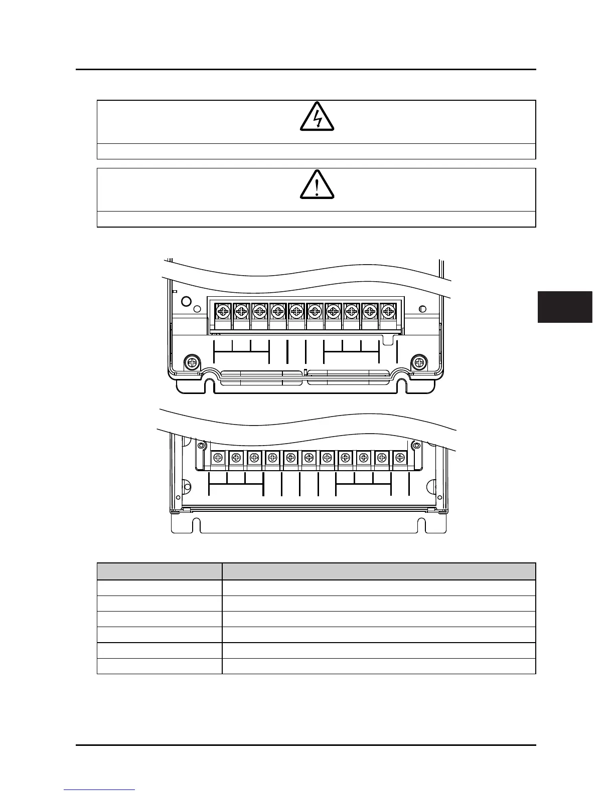
4.3.1 Supply and Motor Terminal
Figure 4–1 Size F2
Figure 4–2 Size F3 - F6
Table 4-4 HD3L supply and motor terminal description
Terminal Description
L1, L2, L3 Three-phase AC power input terminals
U, V, W Output terminals, connect to three-phase AC motor
P1, (+) DC reactor connection terminals
(+), (-) DC supply input terminals; DC input terminals of power regenerative unit
(+), BR Braking resistor connection terminals
PE Ground terminal, connect to the ground
Danger
 Loading...
