Shenzhen Hpmont Technology Co., Ltd. Chapter 6 Function Introduction
HD3L Series Controller User Manual ―61―
6.2.11 F13: Analogue I/O Terminal Parameters
Ref. Code Function Description Setting Range [Default]
F13.00 AI1 function 0 - 2 [0]
F13.01 AI2 function 0 - 2 [0]
F13.02 AI3 function 0 - 2 [0]
F13.03 AI4 function 0 - 3 [0]
0: Unused.
1: Speed setting.
2: Weighing signal.
3: Motor overheat signal input (only AI4 enabled).
• Connect the electronic thermistor embedded motor stator coils to AI4, refer to Figure 4–14, on page
25.
• Refer to parameters F17.01 and F17.02 about the thermistor.
• AI1 input range: 0 - 10V. AI2 - AI4 input range: -10 - +10V.
F13.04 AI1 bias -100.0 - 100.0 [0.0%]
F13.07 AI2 bias
F13.10 AI3 bias
F13.13 AI4 bias
F13.05 AI1 gain -10.00 - 10.00 [1.00]
F13.08 AI2 gain
F13.11 AI3 gain
F13.14 AI4 gain
F13.06 AI1 filter time 0.01 - 10.00 [0.05s]
F13.09 AI2 filter time
F13.12 AI3 filter time
F13.15 AI4 filter time
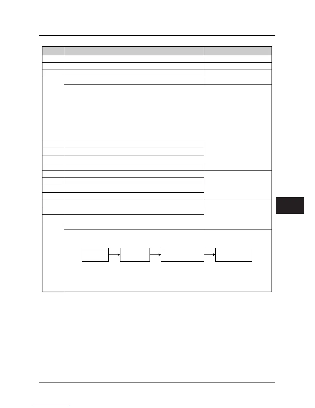
When AI1 - AI4 sets frequency, the relationship between the analogue input and the analogue value after
calculating is shown as figure:
• The formula is: Analogue value after calculating = Gain × Analogue actual value + Bias
• F13.06, F13.09, F13.12 and F13.15 define the filter time.
• The longer filter time is, the higher immunity level is, the response time is prolonged. The shorter filter
time is, the quicker response time is, the lower the immunity level is.
Analogue
actual value
Analogue
input filtering
Analogue input gain
Analogue input bias
Analogue value
after calculating
6
 Loading...
