Chapter 4 Electrical Installation Shenzhen Hpmont Technology Co., Ltd.
―24― HD3L Series Controller User Manual
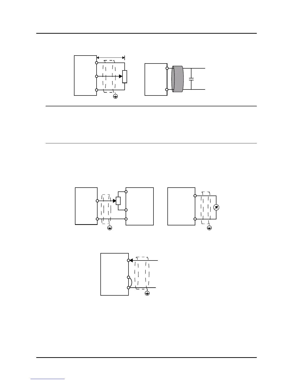
Analogue Input Connection
The AI1 is voltage input and the range is 0 - 10V, as shown in Figure 4–11.
Figure 4–11 AI1 connection
Note:
1. To reduce the interference and attenuation of control signal, length of control cable should limit within 50
m, and the shield should be reliably grounded.
2. In serious interference occasions, the analogue input signal should add filter capacitor and ferrite core, as
shown in Figure 4–11.
AI2/AI3 are selected as voltage input and the range is -10 - +10V. When selecting internal +10V of HD3L,
refer to Figure 4–11; selecting +/-10V external supply, refer to Figure 4–12.
AI2/AI3 are selected as current input and the range is 0 - 20mA, refer to Figure 4–12.
AI3 should correctly set jumper CN2.
Figure 4–12 AI2/AI3 connection
When AI4 is used as setting analogue input terminal, the connection is shown as Figure 4–13. (The
AI4+ = analogue signal input)
Figure 4–13 AI4 connection (AI4 = analogue input terminal)
AI1
GND
GND
AI1
+10
PE
Potentiometer
Signal line winding
 Loading...
