Chapter 4 Electrical Installation Shenzhen Hpmont Technology Co., Ltd
―34― HD5L Series Controller User Manual
4.6.6 HD-PG6-UVW-FD
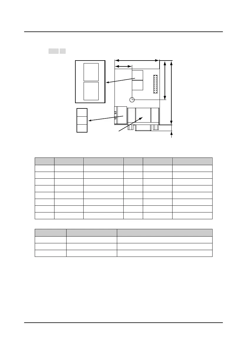
The line drive encoder card with FD output is shown as Figure 4-28. FD switch is shown as the
section 4.6.2 FD Description and the size unit is mm.
Figure 4-28 Line drive encoder card with FD output
Terminal description
Table 4-11 DB15 terminal signal description
1 A+ Differential signal A+ 9 V+ Differential signal V+
2 A- Differential signal A- 10 V- Differential signal V-
3 B+ Differential signal B+ 11 W+ Differential signal W+
4 B- Differential signal B- 12 W- Differential signal W-
5 Z+ Differential signal Z+ 13 PGVCC +5V power supply
6 Z- Differential signal Z- 14 GND Power supply site
7 U+ Differential signal U+ 15 NC NC
8 U- Differential signal U-
Table 4-12 FD output terminal signal description
No. Name Description
1 OUTA FD output signal A, NPN type OC output
2 OUTB FD output signal B, NPN type OC output
3 COM FD output signal site, isolated from GND
30.5
55
6
DB15 terminal
17
44
COM
OUTA
OUTB
ON
ON
1
2
3
1
2
3
FD
low bit
FD
highbit
FD switch
FD output
terminal
 Loading...
