If using a condensate pump, select one approved for use with condensing appliances and furnaces. The pump should have an overflow
switch to prevent property damage from condensate spillage.
It is very important that the condensate piping be no smaller than ¾”. To prevent sagging and maintain pitch, condensate piping should
be supported with pipe supports, and pitched ¼” per foot to allow for proper drainage.
The condensate line must remain unobstructed, allowing free flow of condensate. If condensate freezes in the line, or if line is
obstructed in any other manner, condensate can exit from the tee, resulting in potential water damage to property.
FIRE AND/OR EXPLOSION HAZARD
To avoid serious injury or death, the gas line installation and the gas line inlet pressure test must be done by a licensed professional.
Always match the appliance with the type of gas supplied to the unit (natural gas or LP gas). This appliance must be converted into
propane operation unless specifically manufactured for use with propane. Follow Gas Conversion Manual instructions (separate
document). Propane ready appliances have the suffix “LP” after the model serial number.
Make sure the gas line pressures are within normal limits. Pressures outside normal limits can result in poor performance and
hazardous operating conditions.
This appliance must be converted into propane operation unless it is specifically manufactured to operate on propane. Propane-ready
appliances have the suffix “LP” after the model serial number. Failure to ensure the appliance is set to operate on the provided gas
supply could result in property damage, personal injury, or death.
A. GAS PIPE SIZING TABLES
1. Gas Pipe Sizing
This information is for reference use only. Refer to gas pipe manufacturer specifications for actual delivery capacity. The DOE standard
for Natural Gas is 1100 BTU/ft
3
. Contact the local gas supplier for actual BTU/ft
3
rating.
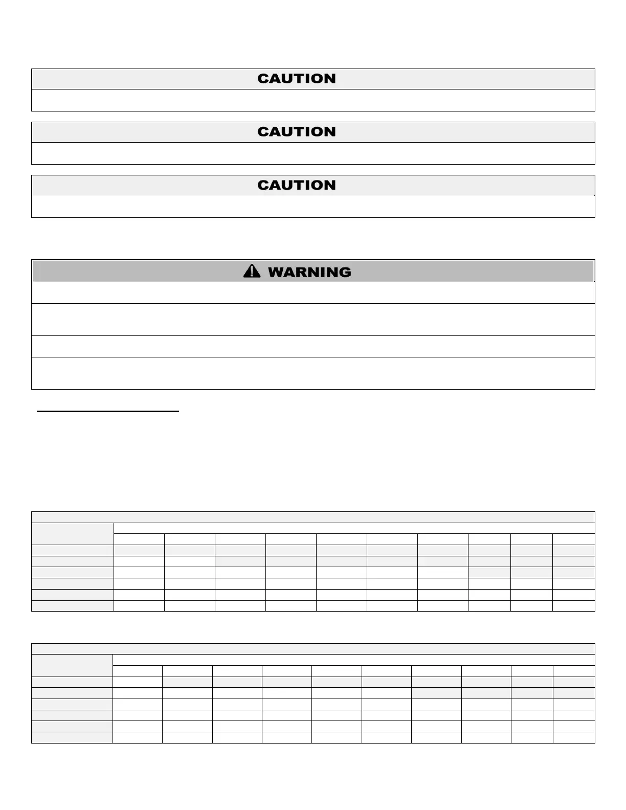
2. Natural Gas Pipe Sizing
The following tables list maximum capacity of pipe in cubic feet of gas per hour for gas pressures of 0.5 psi or less and a pressure drop
of 0.5 inches water column, based on a 0.60 specific gravity for natural gas.
Maximum Natural Gas Delivery Capacity – Length of Corrugated Stainless Steel Pipe in Feet
Cubic Feet per Hour (0.60 Specific Gravity, 0.5 WC Pressure Drop)
Table 13 – Natural Gas Delivery Capacity – Corrugated Stainless Steel Pipe – Refer to ANSI Z223.1 – National Fuel Gas Code,
Latest Edition
Maximum Natural Gas Delivery Capacity – Length of Black Iron Pipe (Sch. 40 Metallic) in Feet
Cubic Feet per Hour (0.60 Specific Gravity, 0.5 WC Pressure Drop)
Table 14 – Natural Gas Delivery Capacity – Black Iron Pipe – Refer to ANSI Z223.1 – National Fuel Gas Code, Latest Edition

 Loading...